Table of Contents
- Introduction
- I. GEMOC Language Workbench

- 1. Overview
- 2. Create a language
- 3. Make a language executable
- 3.1. Make a sequential executable language
- 3.2. Make a concurrent executable language
- 3.2.1. Defining the Domain-Specific Actions (DSA) Project for concurrent language
- 3.2.2. Defining a Model of Concurrency and Communication (MoCC)
- 3.2.3. Exhaustive Exploration and Verification at Language Design Time
- 4. Define an animator
- 5. Compose languages
- 6. Deploy languages
- II. GEMOC Modeling workbench

- 7. Modeling workbench overview
- 8. Editing model
- 9. Executing model
- 9.1. Executing model with the Sequential Engine
- 9.2. Executing model with the Concurrent Engine
- 9.3. Exhaustive Exploration and Verification at Model Design Time
- 10. Coordinating Model Execution
- Bibliography
- Glossary
- Index
List of Figures
- 1. Gemoc Workbenches Global Picture
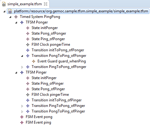
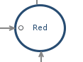
- 1.1. Screenshot of the GEMOC Language Workbench showing the design of a Timed Finite State Machine (TFSM) example.
- 3.1. Screenshot of the First graphical level of Edition in MoCCML.
- 3.2. Screenshot of the Second graphical level of Edition in MoCCML (Constraint Implementation).
- 3.3. The exploration and verification flow in Gemoc
- 3.4. Using T1 Tranformation
- 5.1. Overview of the approach.
- 5.2. Wizard of the examples of coordination.
- 5.3. Windows Problems when languages are not correctly deployed.
- 5.4. Correct deployment of languages and BCOoL operators in the language workbench.
- 6.1. Runtime workbench launch configuration
- 7.1. Screenshot of GEMOC Studio Modeling Workbench on the TFSM example (execution and animation).
- 9.1. Xdsml Wizard
- 9.2. Discovery
- 9.3. Discovery Components
- 9.4. Discovery Clocksystem
- 9.5. Approve licensing
- 9.6. Exploration Graph for an Instance
- 10.1. Wizard of the examples of coordination for the modeling workbench.
- 10.2. BFLoW specification of the coffee machine by using the TFSM and SigPML languages.
- 10.3. Debug Configuration of the Gemoc Coordinated eXecutable Models.
- 10.4. Debug Configuration of the Gemoc Coordinated eXecutable Models with launchers.
- 10.5. Step by step execution of the coordinated models.
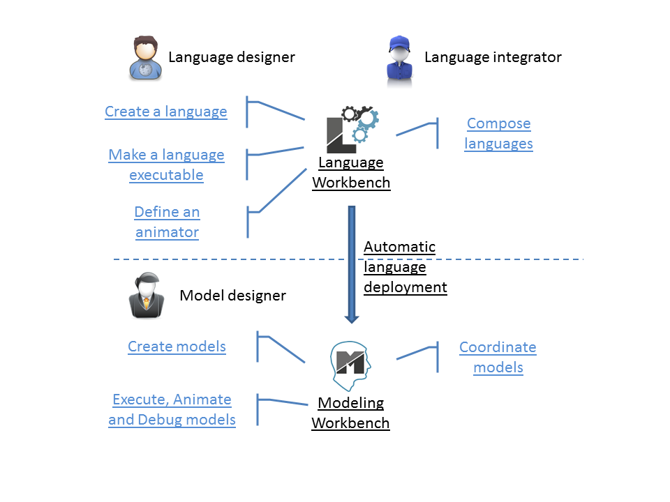
The GEMOC Studio offers 2 main usages:
- Building and composing new executable DSML. This mode is intended to be used by language designers and language integrators (aka domain experts).
- Creating and executing models conformant to executable DSMLs. This mode is intended to be used by domain designers.
Each of these usage has it own set of tools that are referenced as Gemoc Language workbench for the tools for language designers and Gemoc Modeling Workbench for the tools for domain designers.
In this document:
- items or roles relative to the Language Workbench are identified with the following icon :

- items or roles relative to the Modeling Workbench are identified with the following icon :

Note
The latest version of this document is available online from http://gemoc.github.io/gemoc-studio/
The GEMOC Language Workbench allows building and composing new executable DSMLs.
To acheive that, it offers appropriate tools and guidance for the underlying activities wich are grouped in categories.
Build executable language. The first main activity is to build an executable language. The language designer is assited by a dedicated Dashboard to guide him during his work.
This first dashboard groups the activities as follow:
- Create a language
This activity can be decomposed in activities in two groups :
- Domain model (abstract syntax)
- Create the abstract syntax with EMF (incl., the ecore model and the genmodel)
- Model editors (concrete syntax)
- Create a graphical editor with Sirius Designer
- Create a textual editor with Xtext
- Make your language executable
This activity is decomposed in 2 main parts:
- Sequential Execution semantics
- Create the execution semantics with Kermeta and Melange
- Concurrent Execution semantics
- Create the Domain-Specific Actions with Kermeta and Melange
- Create the Domain-Specific Events with ECL
- Create a library of Model of Computation with MoccML
- Define the runtime environnement for the language
- Model Debugger
- Select your breakpointable elements
- Model dynamic representation (for debugging, animation, monitoring)
- Create the graphical representation with Sirius Animator
- Plug your own add-ons
TODO add links to the corresponding sections in the main chapters
TODO: add snapshot of the dashboard
Compose executable languages. The second main activity is to define the composition between executable languages. The language integrator is also assisted by a dedicated dashboard that proposes the following activity groups:
- Compose languages
This activity can be decomposed in activities in two groups :
- Create composition operators
- Create operators with BCOoL
- Combine languages
- Select a set of language to combine
- Apply composition operators to a set of languages.
- Customize composition
TODO: add snapshot of the dashboard
The GEMOC Modeling Workbench allows the use of available languages to create and execute models.
- Create Models
- Use available editors to create domain models.
- Execute and debug models
- Use execution engine
- Use step by step debugger
- Analyse time trace
- Animate models
- Use animation views
The GEMOC Language Workbench is intended to be used by the Language Designers and the Language Integrators. It provides the tools to create and compose eXecutable Domain-Specific Modeling Languages (xDSMLs) using the GEMOC approach.
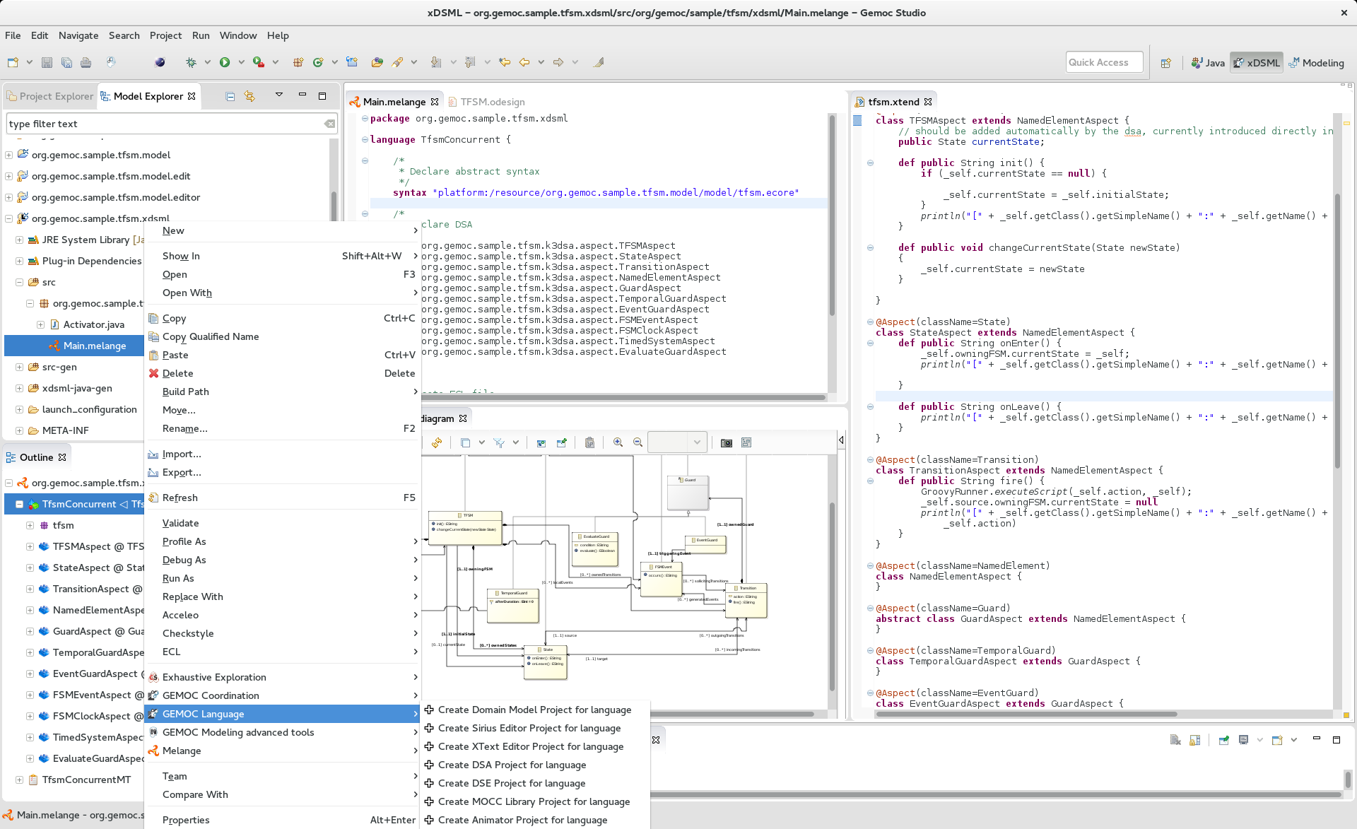
Figure 1.1. Screenshot of the GEMOC Language Workbench showing the design of a Timed Finite State Machine (TFSM) example.
The xDSML Project is the core project of languages created using the GEMOC Studio. It has one main purposes:
- Referencing the different projects implementing the various parts constituting an xDSML;
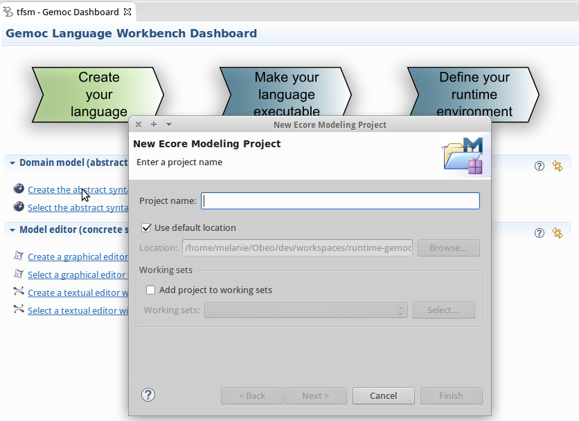
In the GEMOC Studio, go to: File > New > Project… > New GEMOC Language Project. This will create a new xDSML Project in your workspace.
The .melange file is the main element of the xDSML Project.
From the information contained in this file, the project generates additional code that is used by the Execution Engine during the execution of models conforming to the xDSML (see Part II, “GEMOC Modeling workbench ![]() ”).
”).
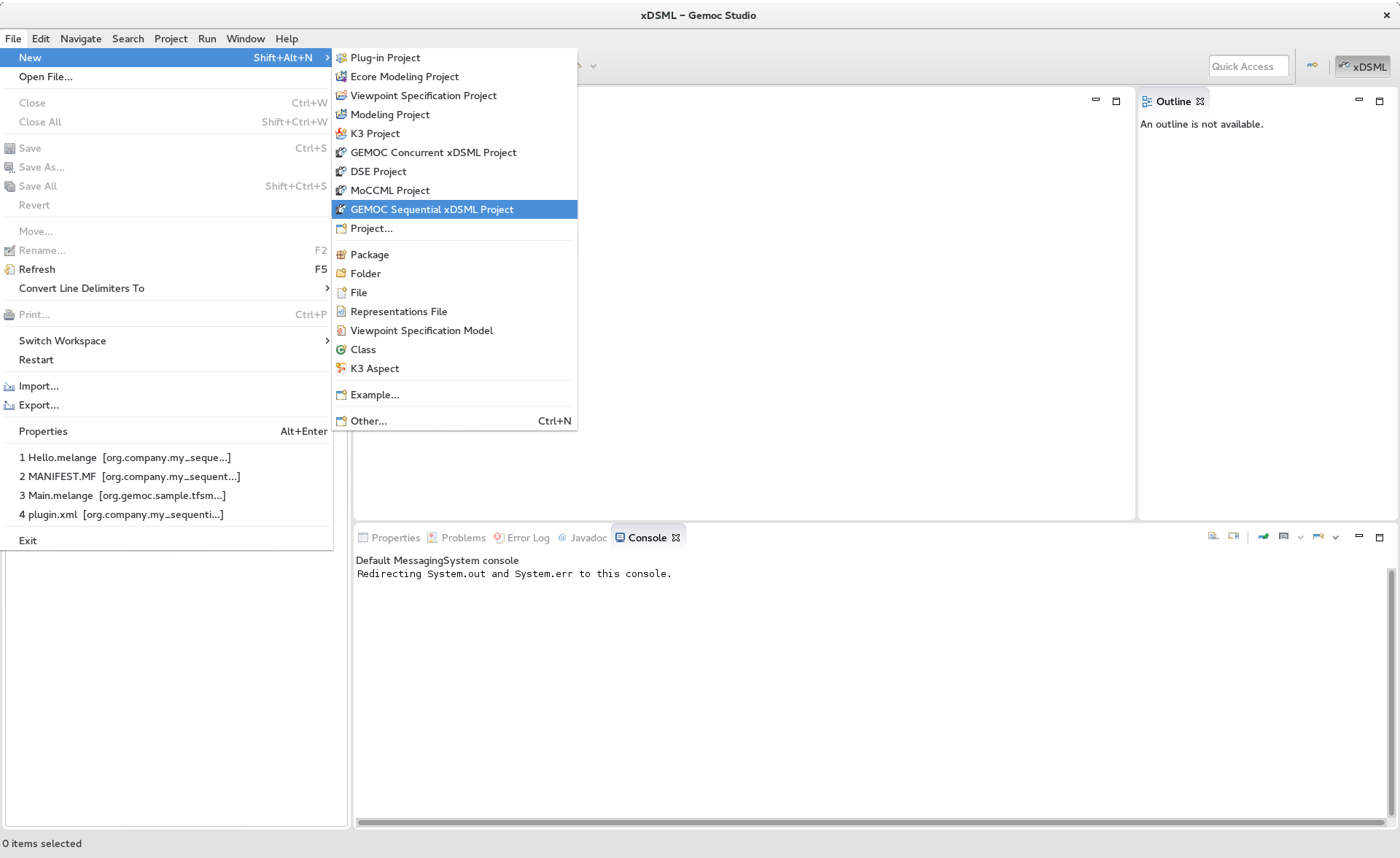
The GEMOC Language Workbench provides an xDSML perspective. It is available in the menu Window > Open Perspective > Other.
This perspective eases the creation of a new xDSML project. In the menu File > New, you have direct access to
- GEMOC Sequential xDSML Project
- GEMOC Concurrent xDSML Project
On a right click on an xDSML project you have access to this menu containing theses commands:
- Generate Multidimentional Trace Addon project for language
- Create Domain Model Project for language
- Create Sirius Editor for language
- Create XText Editor Project for language
- Create Animator Project for language
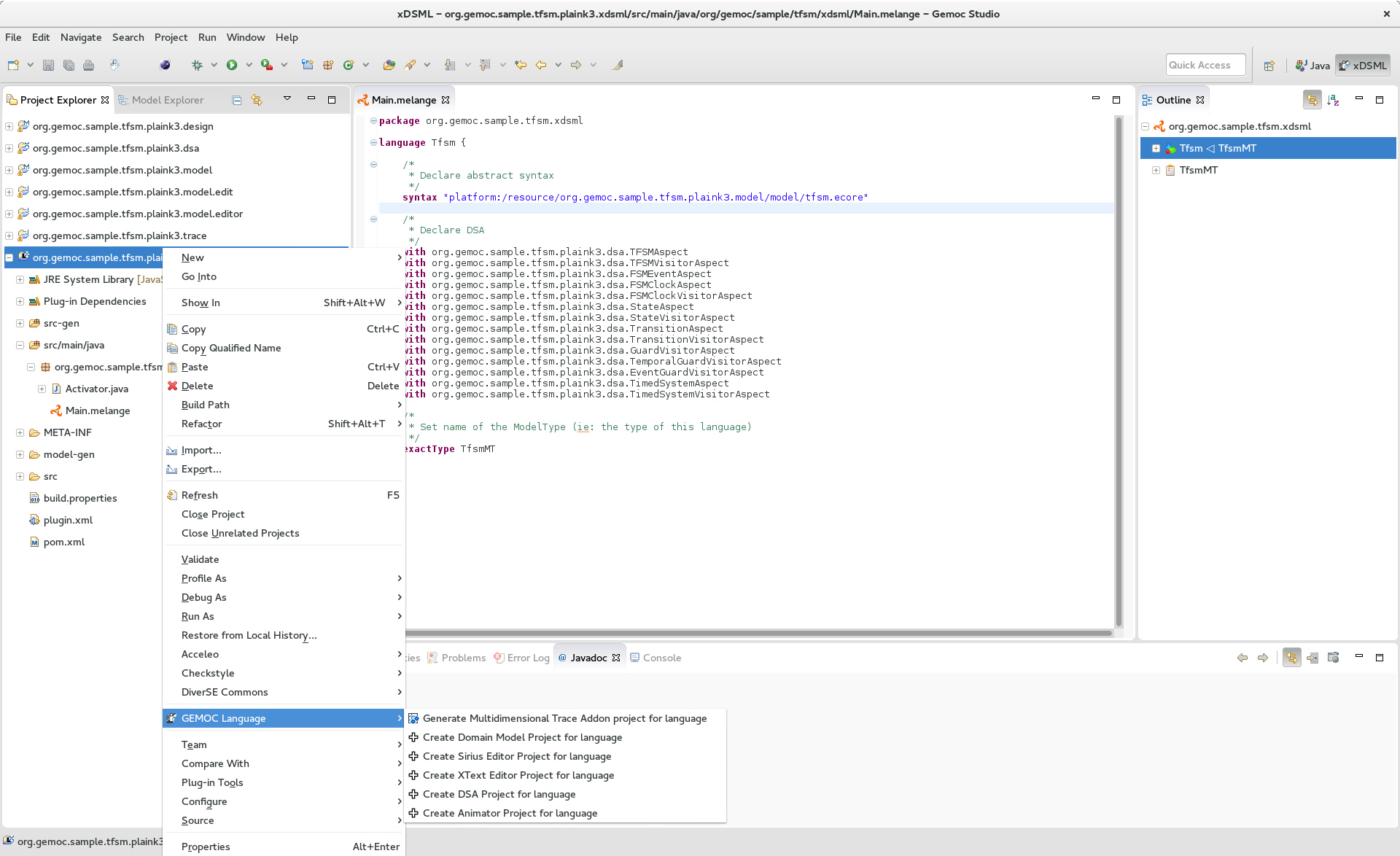
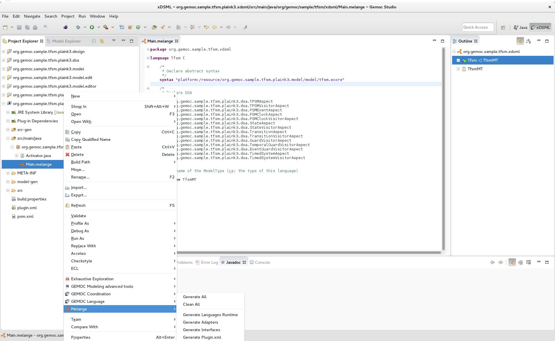
On a right click on a .melange file you have access to this menu containing theses commands:
- Generate All
- Generate Language Runtime, Adapters, Interfaces and Plugin.xml
- Clean All
- Delete generated artifacts
- Generate Language Runtime
- Generate new Eclipse projects for Languages that inherit or with multiple syntax. A new project contains the .ecore merging the multiple Domain models of the Language. It also contains copies of inherited Aspects but applying on the new .ecore file (which has classes in another namespace).
- Generate Adapters
- Generates adaptation classes to see a model as an instance of a compatible Language. (experimental)
- Generate Interfaces
- Generate the ModelTypes as .ecore file. It represents the merge of Domain models and semantics of the Language.
- Generate Plugin.xml
- Generate extension points in the plugin.xml file. They are used by the Modelling Workbench to get informations about defined Languages.
Melange is a Language designing tool. Through a .melange file you can define a Language as an assembly of abstract syntaxes with operational semantics and also as a composition of Languages. To do so, Melange is provided with a textual Languages editor.
A .melange file start with
package your.language.namespace
and contains a list of Language definitions starting with the keyword language.
a basic Language.
package org.gemoc.sample.tfsm.xdsml

language Tfsm {

	/*
	 * Declare abstract syntax
	 */
	syntax "platform:/resource/org.gemoc.sample.tfsm.plaink3.model/model/tfsm.ecore"

	/*
	 * Set name of the ModelType (ie: the type of this language)
	 */
	exactType TfsmMT
}
A Language definition accept theses keywords:
- syntax
- Link your language to your Domain Model. The path to your model follows the Eclipse platform URLs convention: "platform:/resource/<name of your EMF project>/<path to the .ecore file>"
- with
- Link the DSA project to your language. with is followed by the name of a Java class. Melange support wildcard character for this operator. Typing in your language 'with some.package.name.*' will import all classes under this namespace.
- ecl
- Link your language to your ECL project. The intended format for the path to your .ecl file is: "<name of your ECL project>/<path to the .ecl file>"
- inherits
- The keyword inherits allows you to define a Language as an extension of another. It means the abstract syntax and the semantics of the inherited Language are copied in your Language.
Note
Your xDSML project need a dependency to your DSA project. Check the Require-Bundle section in the MANIFEST.MF if the Melange editor can’t see the used Aspect.
a Language with semantic.
package org.gemoc.sample.tfsm.xdsml

language Tfsm {

	/*
	 * Declare abstract syntax
	 */
	syntax "platform:/resource/org.gemoc.sample.tfsm.plaink3.model/model/tfsm.ecore"

	/*
	 * Declare DSA
	 */
	with org.gemoc.sample.tfsm.plaink3.dsa.TFSMAspect
	with org.gemoc.sample.tfsm.plaink3.dsa.TFSMVisitorAspect
	with org.gemoc.sample.tfsm.plaink3.dsa.FSMEventAspect
	with org.gemoc.sample.tfsm.plaink3.dsa.FSMClockAspect
	with org.gemoc.sample.tfsm.plaink3.dsa.FSMClockVisitorAspect
	with org.gemoc.sample.tfsm.plaink3.dsa.StateAspect
	with org.gemoc.sample.tfsm.plaink3.dsa.StateVisitorAspect
	with org.gemoc.sample.tfsm.plaink3.dsa.TransitionAspect
	with org.gemoc.sample.tfsm.plaink3.dsa.TransitionVisitorAspect
	with org.gemoc.sample.tfsm.plaink3.dsa.GuardVisitorAspect
	with org.gemoc.sample.tfsm.plaink3.dsa.TemporalGuardVisitorAspect
	with org.gemoc.sample.tfsm.plaink3.dsa.EventGuardVisitorAspect
	with org.gemoc.sample.tfsm.plaink3.dsa.TimedSystemAspect
	with org.gemoc.sample.tfsm.plaink3.dsa.TimedSystemVisitorAspect

	/*
	 * Set name of the ModelType (ie: the type of this language)
	 */
	exactType TfsmMT
}
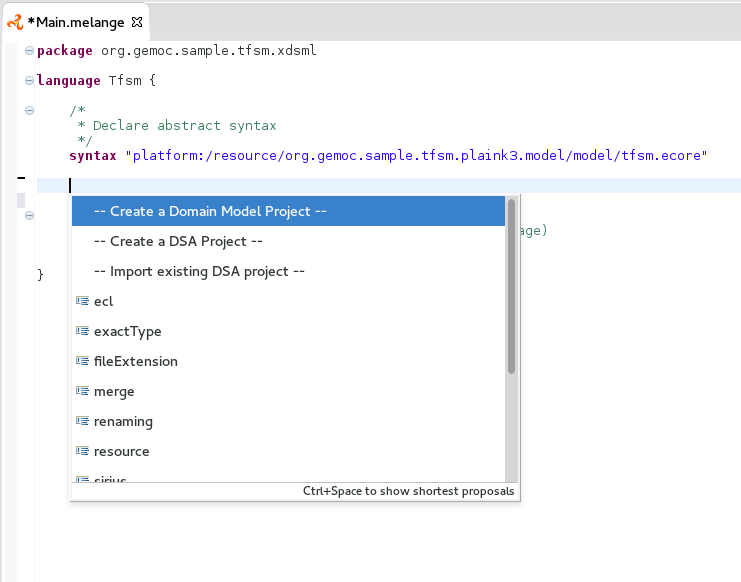
You can press Ctrl+Space to have a content assist in the Melange editor.
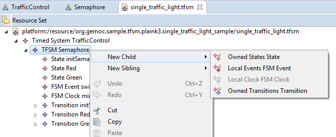
In language { … }
- — Create a Domain Model Project —
- Create a new EMF project and upadte the syntax of your language.
- — Create a DSA Project —
- Create an new K3 project. Based on the syntax of your language, it automatically create Aspects for each class of your Domain. Theses Aspects are also added in your Language.
- — Import existing DSA project —
- Automatically imports all Aspects from a K3 project
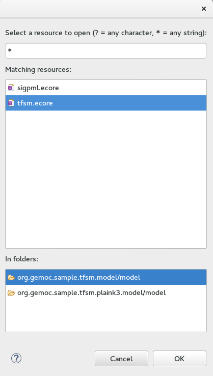
- After syntax
Display the list of available .ecore in your workspace and update syntax with the path to the selection.
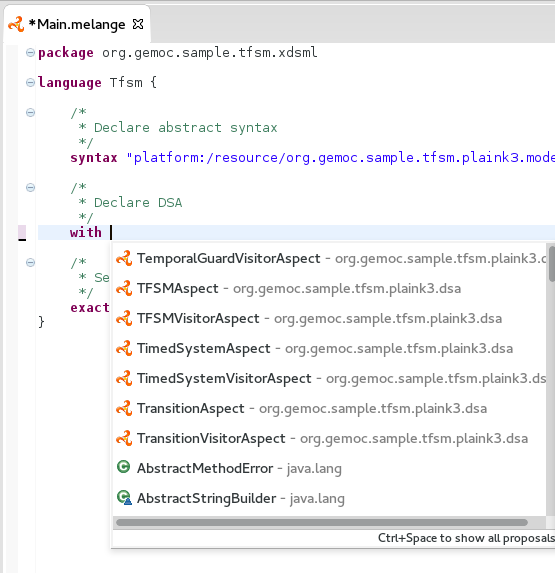
- After with
Display the list of accessible Java classes from your project dependencies. K3 Aspects are displayed first.
- After ecl
Display the list of available .ecl in your workspace and update ecl with the path to the selection.
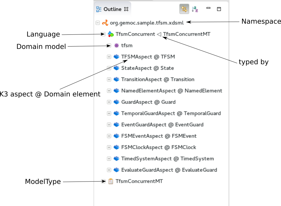
The plugin.xml file is the link between the Languages and the Modelling Workbench. It is mainly composed of two extension points:
- GEMOC extension point: "org.gemoc.gemoc_language_workbench.sequential.xdsml"
- Melange extension point: "fr.inria.diverse.melange.language"
Gemoc extension points declare Languages availables in the Modelling Workbench. It also give the class able to load models for each Language.
GEMOC language.
<extension point="org.gemoc.gemoc_language_workbench.sequential.xdsml">
<XDSML_Definition
modelLoader_class="org.gemoc.executionframework.extensions.sirius.modelloader.DefaultModelLoader"
name="org.gemoc.sample.tfsm.xdsml.Tfsm"
xdsmlFilePath="/org.gemoc.sample.tfsm.plaink3.xdsml/bin/org/gemoc/sample/tfsm/xdsml/Main.melange"
>
Melange extension points declare semantic of Languages as list of Domain model classes associated to their K3 Aspects. It also gives the available entry points for the execution, which are the Aspects methods tagged with @Main.
Melange Language.
<extension point="fr.inria.diverse.melange.language">
<language
aspects="FSMClock:org.gemoc.sample.tfsm.plaink3.dsa.FSMClockAspect,org.gemoc.sample.tfsm.plaink3.dsa.FSMClockVisitorAspect;..."
entryPoints="org.gemoc.sample.tfsm.plaink3.dsa.TimedSystemAspect.main(org.gemoc.sample.tfsm_plaink3.TimedSystem)"
exactType="org.gemoc.sample.tfsm.xdsml.TfsmMT"
id="org.gemoc.sample.tfsm.xdsml.Tfsm"
uri="http://tfsmmt/"
>
Note
<XDSML_Definition name> have to be equal to <language id>
The dashboard is available on .xdsml files from the Project Explorer or the Model Explorer views. See Section 1.1, “xDSML Project” to view how to create an xDSML project.
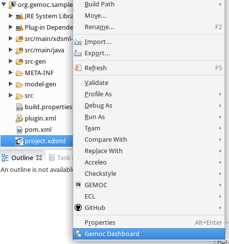
When the Gemoc Dashboard menu is selected a new editor opens.
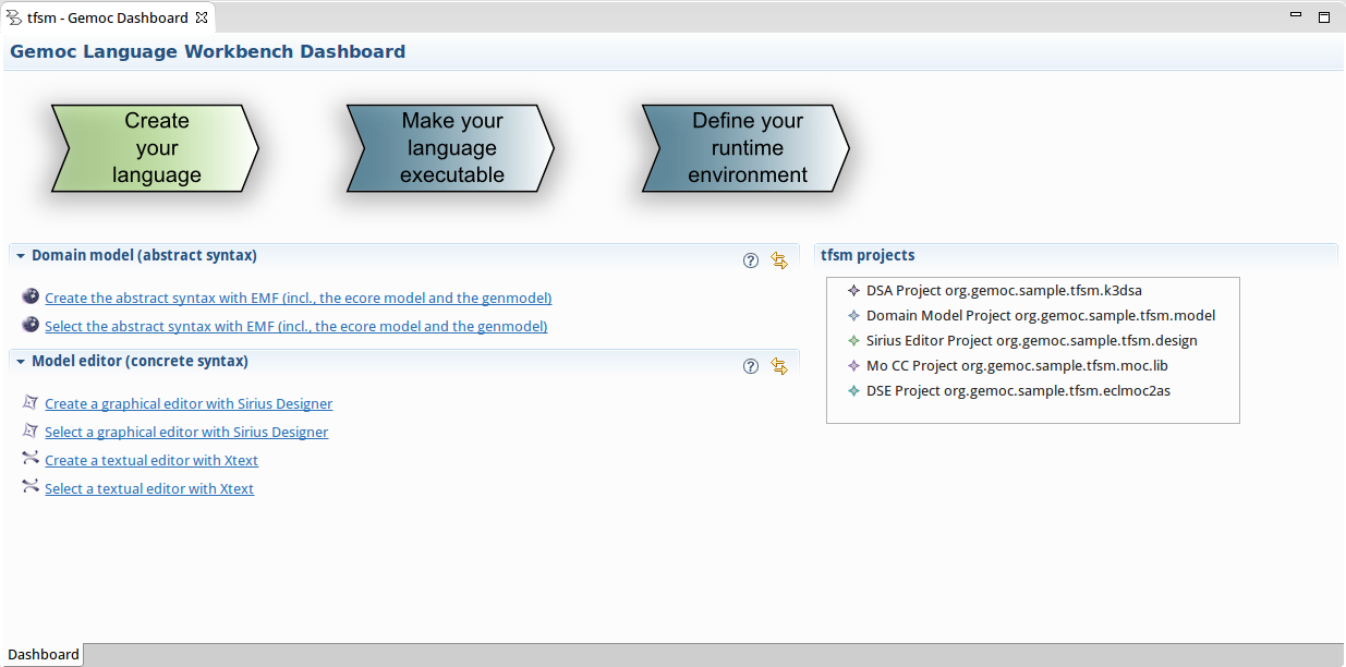
This editor is divided in three main parts:
- Overview part
- Sections part
- Projects view
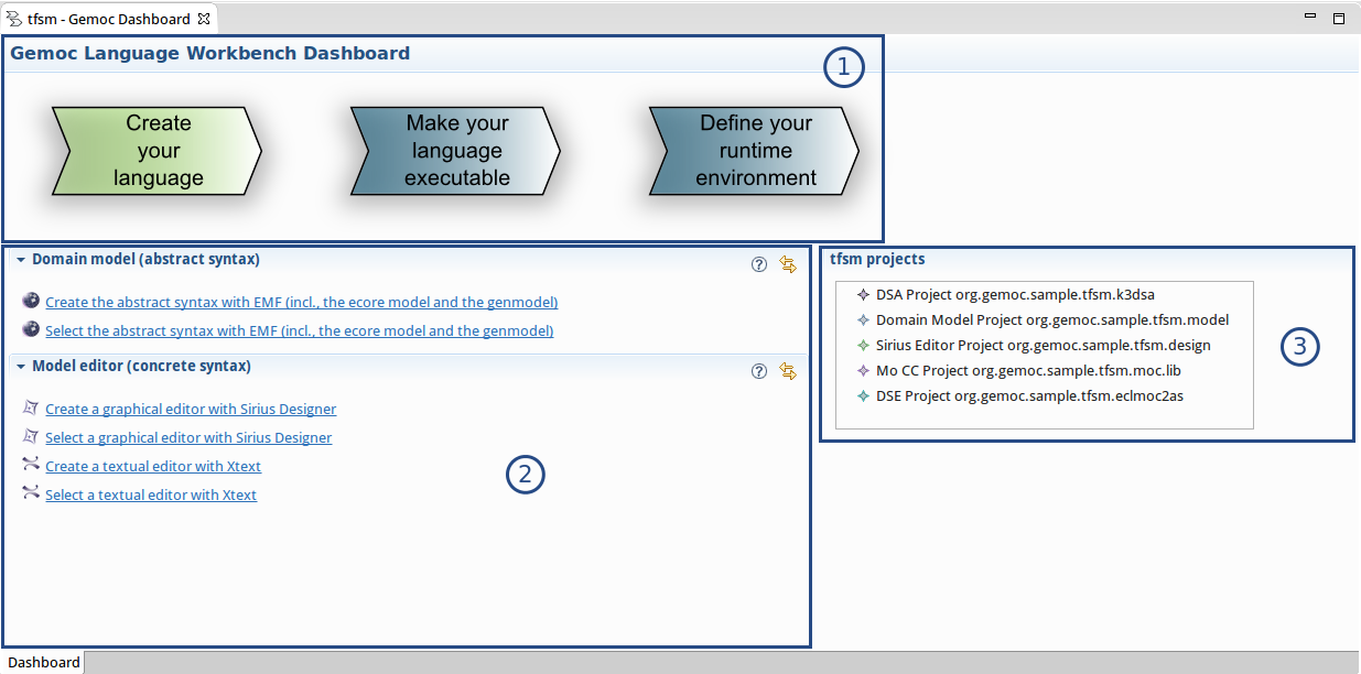
The overview allows to access to the different parts of the Part I, “GEMOC Language Workbench ![]() ” process:
” process:
- Create your language
- Make your language executable
- Define your runtime environment
When you click on a step in the overview the related actions are automatically presented in the sections part.
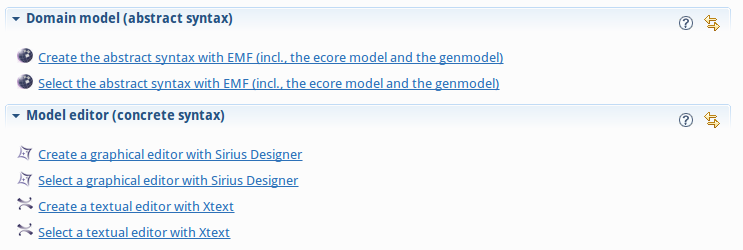
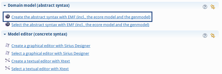
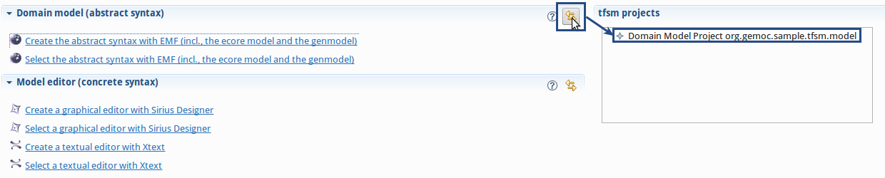
This part provides sections which depends on the selected overview. The sections contain links that can be used to activate the different actions: create the domain model project, edit the DSA project, define a concrete syntax…
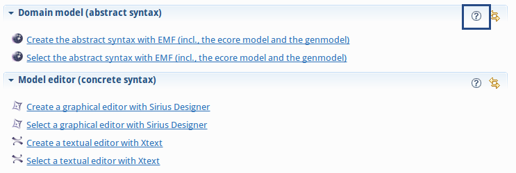
Each section provides a help button which shows the description associated to the section and explains the process step and which actions are available.
On the right side of the dashboard, a tree viewer shows the projects associated to the current xDSML project.
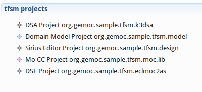
The section toolbar provides a synchronize action. This action filters the content of the tree viewer to keep only projects relevant according to the current process step represented by the section.
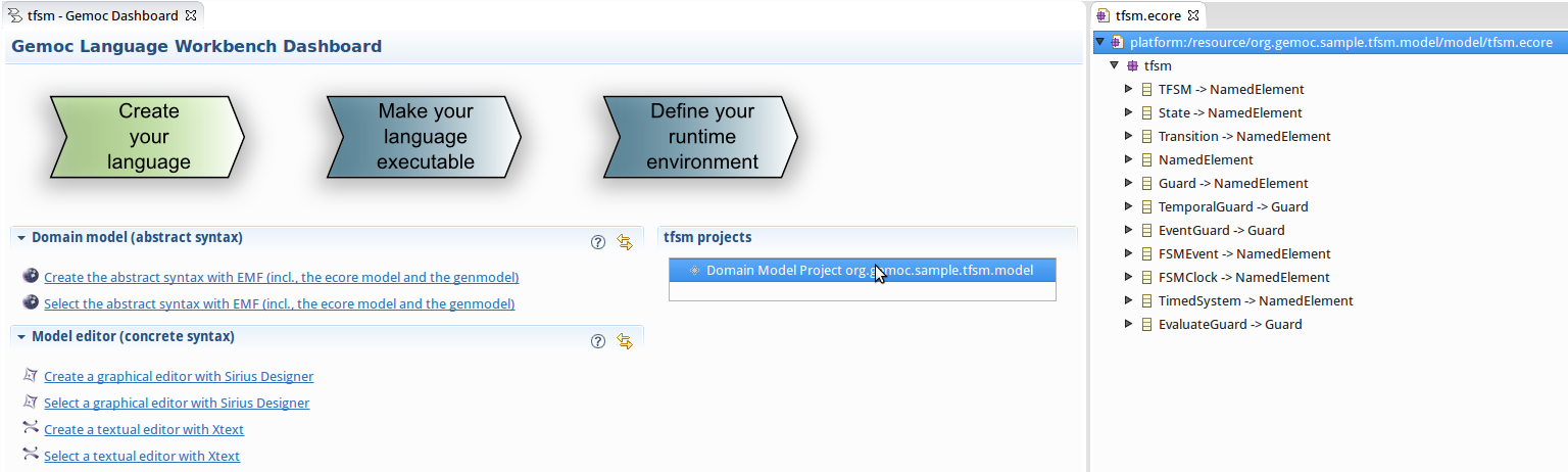
The Domain Model Project specifies the concepts of the domain at hand and the structural relations between the concepts.
The GEMOC Studio relies on the Eclipse Modeling Framework for its Domain Model Projects. See the EMF website for more information on how to create an EMF project in Eclipse. The Domain Model is materialized as an Ecore metamodel.
When your EMF Project is done, connect your xDSML Project to it by specifying in the .melange file the path to your Ecore metamodel thanks the keyword syntax. See Section 1.1.7, “Melange editor” for more informations about Melange keywords and the content assist.
An xDSML can support different concrete syntaxes. Most EMF-based editors should work with GEMOC, however the GEMOC Studio provides additional support for some specific editors. Thus, we recommend using: an EMF arborescent editor, an Xtext editor, and/or a Sirius editor.
See the Xtext website.
If you want to create a graphical concrete syntax you can use Sirius. The Sirius documentation provides information for Sirius Specifier Manual.
EMF provides several services, as seen in Section 2.1, “Defining a Domain Model Project” , EMf allwos to generate many artifacts. In addition to generate the java code for the metamodel and provide a reflective tree editor, EMF allows to generate a customizable Tree Editor.
On the .genmodel right click on the root element then Generate Edit Code and Generate Editor Code.
Some very easy customizations can be done in the .edit project:
- change the icons for each of the metaclasses of yourmetamodel by replacing the
.giffiles in theiconsfolder. - change the displayed labels by providing a custom implementation of the getText methos in the
*ItemProvider.javaclasses.
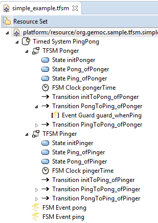
Table Table 2.1, “Example of customization of icons on Timed Finite State Machine tree editor.” illustrates the value of adding dedicated icons for a given domain.
Note
When modifing java code in the generated projects, do not forget to change the comment from generated to generated NOT, so the genmodel generator will keep your changes.
Tip
Providing custom icons and labels are not dedicated to the Tree Editor only. When possible, these elements will also be used to improve the Outline, the Debug Stack or the Variable views (see sections Section 9.2.7, “Debug View”, Section 9.2.8, “Variable View”, Section 9.1.6, “Debug View” and Section 9.1.7, “Variable View”).
Tip
More complex images can be obtained by implementing the getImage method in the *ItemProvider.java classes. For example by using overlay or switching the image depending on one of its attribute in order to represent more precisely the content of model element.
The GEMOC Studio currently supports two major ways to make a language executable :
- one will target a sequential engine
- the second will target a concurrent engine
Note
The underlying executionframework used by the GEMOC Studio can be extended to support other methodologies or engines. However, this isn’t the scope of this document to explain how to use this framework and build an alternate or dedicated engine.
The Domain-Specific Actions define the runtime state (Execution Data) of the model and the operations (Execution Functions) which modify the runtime state of the model. In the case of the sequential engine, this project will also define the (control flow) between the operations.
In the GEMOC Studio, the DSA are implemented using Kermeta 3. To create a new DSA Project, in the main menu of the GEMOC Studio, go to: File > New > Project… > K3 Project. In the wizard, create it as a Plug-in with EMF using the template of your choice. Then, connect the xDSML Project to the DSA by referencing them in the .melange file thanks to the keyword with. See Section 1.1.7, “Melange editor” for more informations about Melange keywords and the content assist.
Kermeta 3 is based on xTend. The Execution Data and Execution Functions are defined through aspects weaved onto the metaclasses of the Domain Model.
The Execution Data consist in attributes and references added to existing concepts (metaclasses) of the Abstract Syntax. They may also include new metaclasses which define the type of these new attributes and references.
The Execution Functions define how the Execution Data evolve during the execution of the model. Execution Functions can be implemented by defining the body of a method.
These methods must have the @Step annotation.
Whenever a method with an @Step annotation returns, the changes in the model will be applied (via a transaction) to the resource. This means that the changes will be visible from an animator.
The technology used be K3 with its @Step annotation allows nested call so that changes in the model will be applied when entering and leaving methods having this annotations.
Note
Any change to the model must be done by operations with the @Step annotation or that are called by an operation that have the annotation.
Defining the control flow between operation for the sequential engine is equivalent to write a Visitor where operations can call other operations. This is quite straightforward with K3 @Aspect annotation since the operations are directly weaved on the metaclasses and applied on the target model elements.
The Domain-Specific Actions define the runtime state (Execution Data) of the model and the operations (Execution Functions) which modify the runtime state of the model.
In the GEMOC Studio, the DSA are implemented using Kermeta 3. To create a new DSA Project, in the main menu of the GEMOC Studio, go to: File > New > Project… > K3 Project. In the wizard, create it as a Plug-in with EMF using the template of your choice. Then, connect the xDSML Project to the DSA by referencing them in the .melange file thanks to the keyword with. See Section 1.1.7, “Melange editor” for more informations about Melange keywords and the content assist.
Kermeta 3 is based on xTend. The Execution Data and Execution Functions are defined through aspects weaved onto the metaclasses of the Domain Model.
The Execution Data consist in attributes and references added to existing concepts (metaclasses) of the Abstract Syntax. They may also include new metaclasses which define the type of these new attributes and references.
The Execution Functions define how the Execution Data evolve during the execution of the model. Execution Functions can be implemented by defining the body of a method.
Note
For now, Execution Functions are considered as atomic, instantaneous and blocking. This means that any long computation will block the rest of the simulation, and concurrent Execution Functions are not executed in concurrence yet.
Warning
For technical reasons, the Domain Model (Ecore metamodel) must specify the signature of the Execution Functions as EOperations.
It is possible to test the DSA (in particular the Execution Functions) by simply writing a simple program with a main function (using Java or Xtend/Kermeta3). Create or load a model conform to your Domain Model and call the Execution Functions in the right order to verify there are no runtime exceptions or domain issues.
In the GEMOC approach, the executability characterization for a given language is done through several steps that include: the description of the actions associated with the language concepts (i.e. the Executions Functions); the description of the data / attributes that capture the state of a model or its evolution (the Execution Data); the description of the underlying language model of concurrency (the MoCC constraints).
A Model of Concurrency and Communication (MoCC) represents the concurrency, synchronizations and the possibly timed causalities in the behavioral semantics of a language. It must represent the acceptable schedules of the atomic actions of the language, which represent both computation and communication.
In this part of the guide, we assume that achieving the first two points has already been done based on Section 3.2.1, “Defining the Domain-Specific Actions (DSA) Project for concurrent language”. In this part, we will mainly focus on the steps for the description and integration fo the model of concurrency in the language, once the EF and ED have been already taken into account and integrated to the language. The execution engine of the GEMOC Studio is based on an event-based semantics, which means that events are used to activate the EF actions that can change the state of a model.
To describe and integrate the model of concurrency, we must 1) have a description of the useful events allowing activation of the EF, 2) a mechanism to express the MoCC constraints that apply on these events.
To enable the automatic generation of the execution model of a given DSML model, the MoCC is weaved into the context of specific concepts from the abstract syntax of the DSML. This contextualization is defined by a mapping between the elements of the abstract syntax and the constraints of the MoCC (defined using MoCCML). Examples of mapping are shown below.
The mapping defined in MoCCML is based on the notion of event, inspired by ECL ECL Description, an extension of the Object Constraint Language OCL. The separation of the mapping from the MoCC makes the MoCC independent of the DSML so that it can be reused.
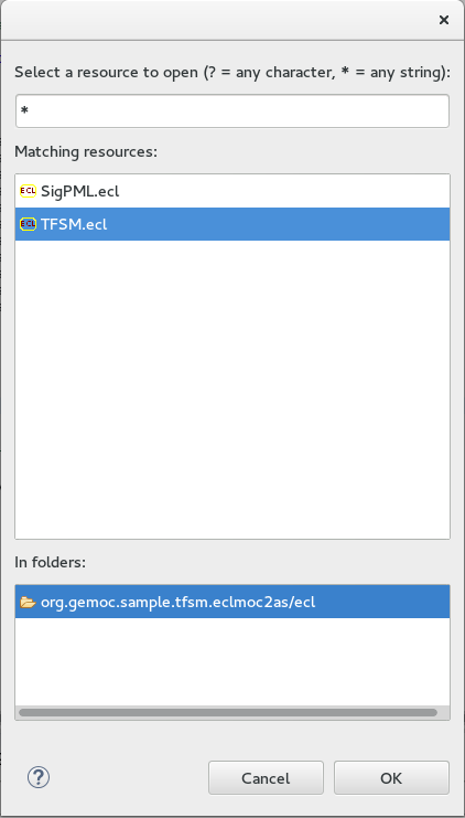
ECL models are created via files with the extension .ecl. The _xDSML environment enables the creation and / or opening of new ECL project Section 1.1, “xDSML Project”.
In this section, we show an examplified way to use ECL. The required steps to go from a given language to the integration of its concurrency model are presented.
As shown in Listing ???, an ECL file imports the extended language that contains the language metaclasses, the EF and ED. The ECL language defines the notion of import to import the extended metamodel (see import of dplExtended.ecore in Listing ???). The import is used to load all the concepts of language that are used to clarify: the EF activation events; static properties numeric or Boolean values, and constraints associated with concepts.
import "platform:/resource/org.gemoc.model.dpl.dplextended/model/dplExtended.ecore"
The ECL model gives access to the concept of the language via the declaration of their package container. In the illustration below, the package container is dplextended. Every metaclass/ concept is declared as a context. In a given context, we define the mapping between events and actions and the MoCC constraints of the context. The illustration shows the definition and mapping of events associated with the concept of Philosopher. For the context Philosopher, the events are used to enable its actions ie eat() and think() actions. ECL syntax for declaring the mapping Event / Action is as follows:
Define the type of the event: def: think: Event
- When the event activate actions: the action associated to the event is accessed through the context via self.actionName() (e.g. in Listing ??? Philosopher self.think() and self.eat())
- When the event does not trigger an action i.e. used as internal control events : Its declaration does not mention any related action (e.g. getrightFork, getleftFork, putrightFork, putleftFork)
- Finally, we can define local attributes to capture the value of static properties that can be for instance integers or booleans (e.g. def: eatcycleMax: Integer = self.eatCycles) The above steps specify the declaration of events and attributes that are used to control the actions for each language concept. We can focus on the description of the model of concurrency defined using MoCCML.
package dplextended
	context Philosopher
		def: think : Event = self.think()
		def: getrightFork : Event = self
		def: getleftFork : Event = self
		def: eat : Event = self.eat()
		def: putrightFork : Event = self
		def: putleftFork : Event = self
		def: thinkcycleMax : Integer = self.thinkCycles
		def: eatcycleMax : Integer = self.eatCycles
endpackage
The latter phase is done in two steps: the implementation of the execution control constraints with MoCCML; the use of these constraints in the context definition to specify how the events should be scheduled (determine their causalities).
This section presents the MoCCML editor that supports the edition of MoCC_s. To keep the defined models formal and to provide a solver for the _MoCC, an operational semantics and a solver based on this formal semantics were defined. For more information on the operational semantics the reader can refer to MoCCML Operational Semantics.
The MoCCML models are created via files with an .moccml extension. They are also natively created from the dashboard _xDSML, where you can create a MoCC project. The project defines an empty model _.moccml with just the name of the library to be created. For a graphical representation of the models, you have to right-click on the file (New Representation File) and run next until the creation of the _.aird representation. This procedure is described in the Sirius tutorial Sirius documentation and Sirius Specifier Manual to create new diagrams starting from a model whose graphical editor was made from Sirius.
MoCCML is a declarative meta-language specifying constraints between the events of a MoCC. At any moment during a run, an event that does not violate the constraints can occur. The constraints are grouped in libraries that specify MoCC specific constraints. The constraints are eventually instantiated to define the execution model of a specific model. The execution model is a symbolic representation of all the acceptable schedules for a particular model. MoCCML is based on the principle of defining constraints on events. There are two categories of constraint definitions: the Declarative Definitions and the Constraint Automata Definitions. Each constraint definition has an associated ConstraintDeclaration that defines the prototype of the constraint.
The concrete syntax of MoCCML is implemented as a combination of graphical and textual syntaxes to provide the most appropriate representation for each part of a MoCC model library. The graphical syntax can be divided into two levels of representation: one for the definition of the MoCC libraries (the declaration and definition of the automata constraints); another for the implementation of the constraints in the form of automata. For instance:
- The first level of representation contains elements as illustrated in Figure Figure 3.1, “Screenshot of the First graphical level of Edition in MoCCML.”. The represented model imports two CCSL libraries (kernel.ccslLib and CCSL.ccslLib). The imported libraries provide predefined types that are used to define formal parameters such as DiscreteClocks, Integers, etc. Each defined Relation Declaration is associated to a Automata constraint definition. The association is done through the Set Declaration Relation link.
- The second level of graphical representation defines the graphical syntax for the modeling of the Automata constraints.
- The overall MoCC models are serialized to a textual syntax, which means that the graphical models are transformed into their equivalent representation in a textual formal. Both representations (graphical or textual) can be used for edition of models. Moreover, we define the integration of an embedded textual editor in the graphical representation to focus on specific parts of the MoCC model that are better edited using a textual syntax (eg trigger, the guards and the actions on transitions). Embedded editors are called by double-clic, and are placed on specific graphical edition elements (Relation Declaration, Relation Definition, DeclarationBlock, Transition).
NB: MoCCML has multiple pallets to instantiate a library. The pallets are located on the right branch of the editor. The creation of new library is preceded by an import of the native CCSL libraries (kernel.ccslLib, CCSL.ccslLib) which provide primitives for the description of events and variables that are handled by the constraints in the MoCC library. We use the third pallet in Figure Figure 3.1, “Screenshot of the First graphical level of Edition in MoCCML.”to import such CCSL libraries.
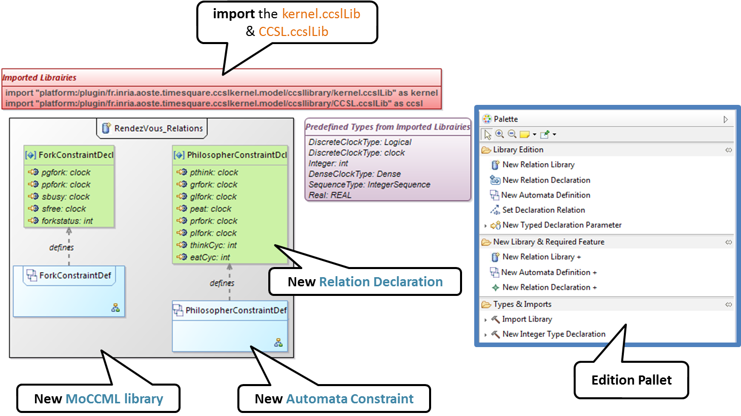
As shown in Figure Figure 3.1, “Screenshot of the First graphical level of Edition in MoCCML.”, creating new MoCC libraries can be done by using the first two pallets on the right (Library Edition, New Library & Required Feature). In these pallets, the element (Library New Library + New Relationship and Relationship) can be used for the instantiation of a new MoCC library. The two are distinguished by the fact that the last mentioned will create a new library of MoCC, while adding a default Relation Declaration. In Figure Figure 3.1, “Screenshot of the First graphical level of Edition in MoCCML.” we create a new Library called RendezVous_Relations.
In a MoCC library, we define constraints and their declarations. The declarations identify events and parameters to be considered in the implementation of the constraint. In the editor, the declaration is made using the two above mentioned pallets, and using the elements in the pallets i.e.: New Relationship Declaration and New Relationship Declaration +. The two differ in that the latter creates a Relation Declaration with a default formal parameter declaration. In the Figure Figure 3.1, “Screenshot of the First graphical level of Edition in MoCCML.”, we create two relation declarations (ForkConstraintDecl and PhilosopherConstraintDecl). Listing ??? also shows the equivalent textual code generated for the PhilosopherConstraintDecl.
RelationDeclaration PhilosopherConstraintDcl(
			pthink : clock,
			grfork : clock,
			glfork : clock,
			peat : clock,
			prfork : clock,
			plfork : clock,
			thinkCyc:int,
			eatCyc:int
		)
The implementation of constraints can be specified textually or graphically. Graphically, the first two pallets are used to create new definitions of constraints associated with their declarations. Constraint definitions is done using the menu items (New Automata Definition and New Automata Definition +). In Figure Figure 3.1, “Screenshot of the First graphical level of Edition in MoCCML.”, the following constraints are specified: ForkConstraintDef, PhilosopherConstraintDef). At this stage, we toured the main notions that can be set on the first level of graphical description with MoCCML. To navigate in the second level of graphical description (Constraint implementation), one should right-click on a specified constraint definition using (Open Diagram / New Diagram). Open Diagram will navigate to an existing diagram; New Diagram will create a new diagram to edit. The MoCCML Editor offers 3 different pallets for: editing the automata, defining the local variables and editing the transitons (ie adding Trigger, Guard, Actions). Figure Figure 3.2, “Screenshot of the Second graphical level of Edition in MoCCML (Constraint Implementation).” shows a simple example with two control states. An additional Layer displays the details of the transitions (Trigger, Guard, Action) as shown in Figure Figure 3.2, “Screenshot of the Second graphical level of Edition in MoCCML (Constraint Implementation).”, see yellow boxes. Besides, editing DeclarationBlock boxes and details in Transitions can be done using embedded text editor by double-clicking on the related boxes. We can then edit the properties of transitions and local variables textually.
One can define the desired set of constraints on the concepts of language using the MoCCML editor. To see the text code corresponding to the serialization of the edited MoCC models, the user can open the _.moccml file. Editing can also be directly made from this file and all the changes will be reflected in the graphical editor. The use of constraints is shown in the next section.
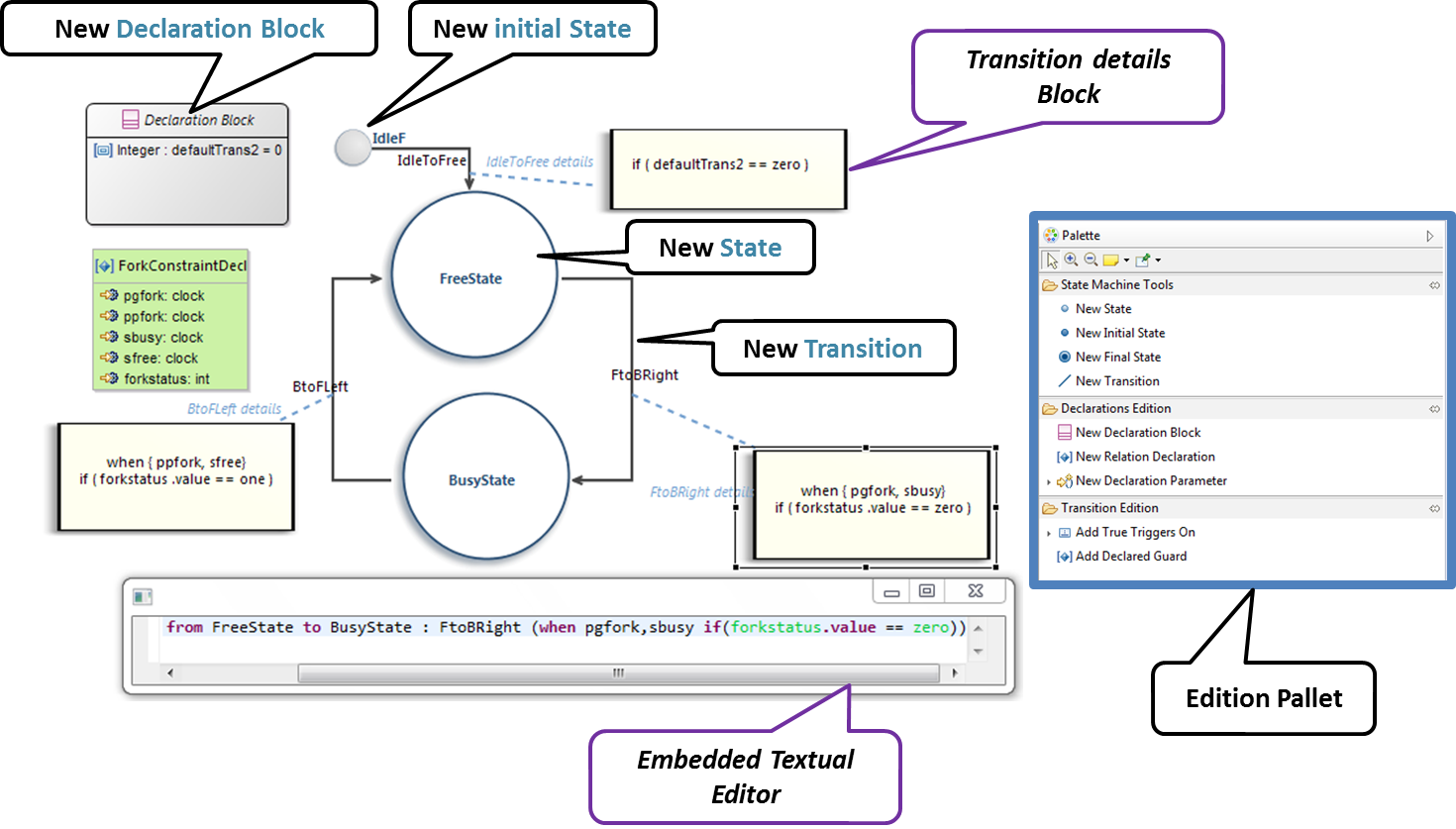
Figure 3.2. Screenshot of the Second graphical level of Edition in MoCCML (Constraint Implementation).
The MoCC constraints models can be used in the ECL file on concepts which they are attached. To declare the constraint on the events, we re-declare the context of the concept then define an invariant inv, see Listing ???. In this listing we also import the MoCCML library that was defined previously (i.e. rendez_vous.moccml) For instance, the invariant related to the context Philosopher (PhilosopherConstraintInv) uses the PhilosopherConstraintDef via its PhilosopherConstraintDcl declaration? It takes as input the set of control events and static variables used to calculate the causality between events.
ECLimport "platform:/resource/org.gemoc.dpl.xdsml.mocc.model/mocc/rendez_vous.moccml"
ECLimport "platform:/plugin/fr.inria.aoste.timesquare.ccslkernel.model/ccsllibrary/kernel.ccslLib"
ECLimport "platform:/plugin/fr.inria.aoste.timesquare.ccslkernel.model/ccsllibrary/CCSL.ccslLib"

package dplextended
	context Philosopher
		def: think : Event = self.think()
		def: getrightFork : Event = self
		def: getleftFork : Event = self
		def: eat : Event = self.eat()
		def: putrightFork : Event = self
		def: putleftFork : Event = self
		def: thinkcycleMax : Integer = self.thinkCycles
		def: eatcycleMax : Integer = self.eatCycles

	context Philosopher
	inv PhilosopherConstraintInv:
		Relation PhilosopherConstraintDcl(
                self.think,
                self.getrightFork,
                self.getleftFork,self.eat,
                self.putrightFork,
                self.putleftFork,
                self.thinkcycleMax,
                self.eatcycleMax
                )
endpackageOne benefit of assigning an execution semantics onto a DSL is to pave the way for exhaustive exploration. Exhaustive exploration is a technique used in complex and safety system design to ensure the correct adequacy between the system requirements and the real behavior of the system. This is made possible by exploring and verifying properties on an exhaustive finite state space of the system representing the whole set of relevant configurations your system may reach.
Gemoc provides the first step towards exploration and verification by building the graph of all the possible schedules of a system model constrained with MoCCML. It can then be used in a model-checking tool to verify behavioral properties of the MoCCML models. Thanks to Gemoc approach the execution model is explicited and can be manipulated to for instance:
- Verify temporal logic properties (safety and liveness) on the state space graph structure;
- Extract a schedule that optimizes specific objectives;
- Extract system properties by static analysis of an event-graph representation of the execution model.
In the Gemoc approach the steps toward exploration and verification during language design are:
- Define an executable model and its mapping on a DSL(we assume it has already been defined see Section 3.2.2, “Defining a Model of Concurrency and Communication (MoCC)”);
- Generate a configuration file from ECL model to target an exhaustive exploration tool;
In the Gemoc approach the steps toward exploration and verification during modeling design are described in Section 9.3, “Exhaustive Exploration and Verification at Model Design Time”: The flow toward exhaustive exploration and verification in Gemoc is presented in figure Figure 3.3, “The exploration and verification flow in Gemoc” and described in the following sections.
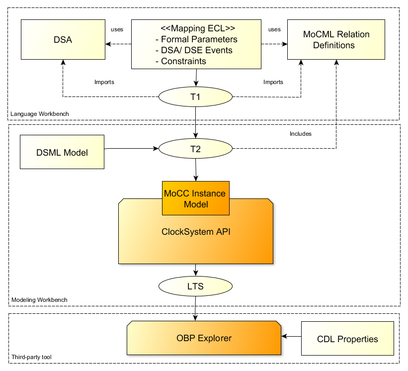
ECL specification is the starting point toward exploration. In this specification we define events associated with the actions of the DSA and also events associated with the DSE events. On these event bindings we apply the MoccML relations of the MoC Library to schedule the events. A finite state space of a system uses such scheduling constraints and therefore a configuration file to target an exhaustive exploration tool must be generated:
T1 transformation generates a configuration file to later target exhaustive exploration or simulation tools. T1 takes as input the ECL mapping definition between the DSL and the MoCCML to generate a transformation T2 describing transformation rules that will be used to produce the processes for the DSL related functions and data (DSA) and the behavioral processes corresponding to the MoCCML constraints.
T1 is automatically generated from ecl model and results are stored in mtl-gen folder.
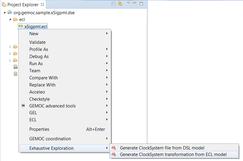
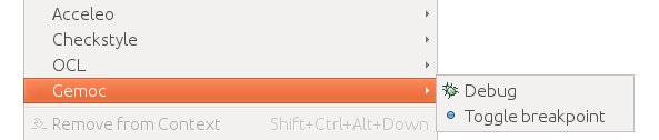
However to execute T1 manually right-click on the ECL file → ![]() Exhaustive Exploration →
Exhaustive Exploration → ![]() Generate ClockSystem transformation from ECL model as illustrated in figure Figure 3.4, “Using T1 Tranformation”.T2 is generated in the repository <mtl-gen>.
Generate ClockSystem transformation from ECL model as illustrated in figure Figure 3.4, “Using T1 Tranformation”.T2 is generated in the repository <mtl-gen>.
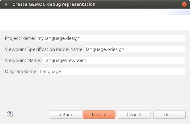
The debug layer is an extension on top of a graphical editor defined with Sirius which represents runtime data and the current instruction. See Section 2.2.2, “Defining a Concrete Syntax with Sirius” for more details about Sirius. This section covers the debug representation creation wizard and the technical implementation details. Technical implementation details are only useful for advanced use case and troubleshooting.
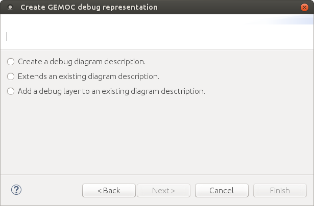
This wizard creates a layer to represent the current instruction and add commands in order to manage breakpoints and launch a simulation in debug mode. This is a default implementation, it can be customized to represent runtime data for instance. The customization uses the Sirius description definition, see the Sirius Specifier Manual for more details. The wizard presents three ways to implement this layer:
- Create a debug diagram description
- Extend an existing diagram description
- Add a debug layer to an existing diagram description
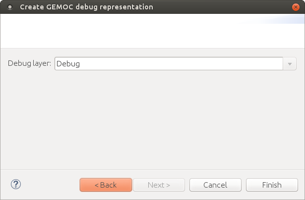
It creates a diagram representation with a default debug layer. The representation does not depend on another representation. A typical use case is a language where the runtime data representation is too far from the language graphical syntax.


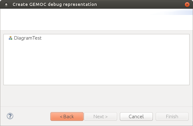
It creates a diagram representation with a default debug layer that extends an existing representation. This allows to have a debug layer based on the representation of the language concrete syntax. The language concrete syntax can be deployed without the debug representation. A typical use case is the reuse of an existing diagram definition that you cannot modify by yourself. For instance if you want to use UML, you can reuse the UML Designer.
You can select any diagram description.
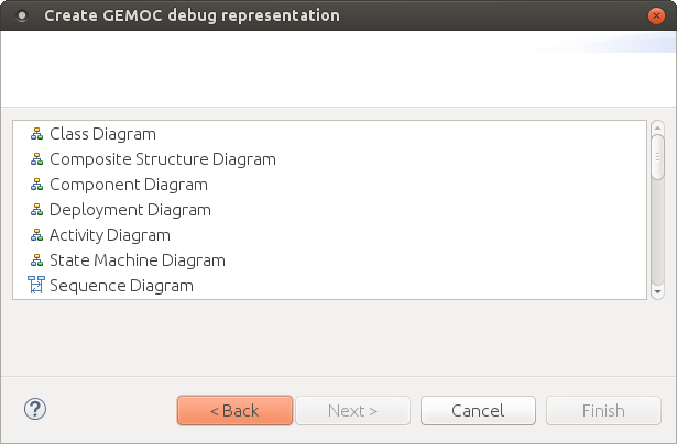
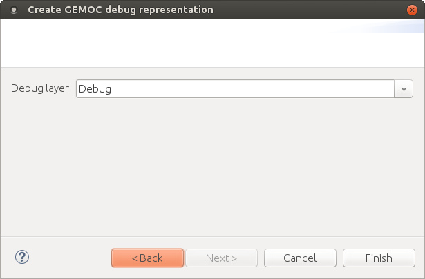
And then define the new diagram description which extends the one you previously selected.
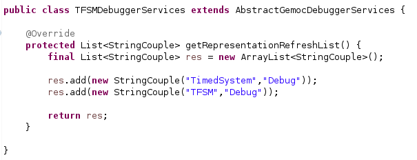
Implementation details are for advanced use and troubleshooting. It explains how the implementation works behind the scene. There are two main elements covered here : the debugger services class and the debug layer itself.
The debugger services class is use to tell which representations should be activated and refreshed during debug (see the getRepresentationRefreshList() method). It also provides a method to know if an element of the diagram is the current instruction. This is provided by the isCurrentInstruction() method.
The default debug layer adds action to start the simulation in debug mode and to toggle breakpoints (1). When a breakpoint exists for an element of the diagram, a visual feedback is displayed according to the breakpoint state (2). The current instruction is also highlighted in yellow by default (3).
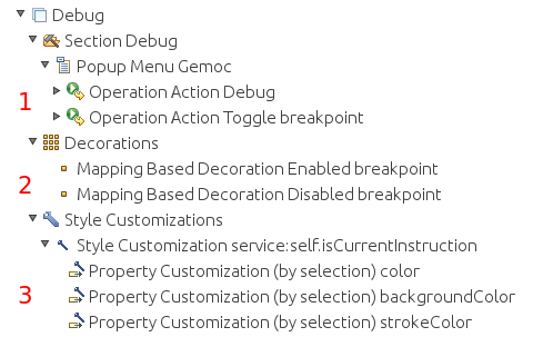
This is a default debug layer, it can be customized to fit your needs. The customization use the Sirius description definition, see the Sirius Specifier Manual for more details.
The multidimentional trace is a mecanism that enable some extra feature in the debugger in the Modeling workbench. This turns the debugger into an omniscient debugger with forward/backward features and advanced visualization of data changes in the model.
This feature can be enabled by using the generator on top of the xdsml project and generate the Trace Addon Project.
TODO complete this section.
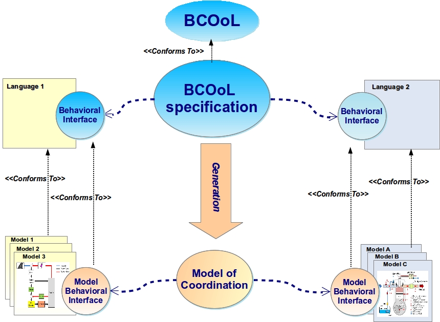
BCOoL is a dedicated language to explicitly specify coordination patterns, i.e., to specify, at the language level, how some models conforming to different DSMLs can be coordinated. This enables the integrator to capture the knowledge of integration of systems. In BCOoL, the specification relies on Operators. Once an operator is defined between different DSMLs, it can be used to generate a coordination model between any models conforming the DSMLs used in the operator.
BCOoL is developed on top of the eclipse platform as a set of plugins. More precisely, it is integrated to the GEMOC studio.
BCOoL is based on the EMF and its abstract syntax has been developed using Ecore (i.e., the meta-language associated with EMF). The textual concrete syntax has been developed using Xtext, providing advanced editing facilities.
BCOoL adds coordination facilities to the GEMOC studio. In the language workbench, an integrator can develop BCOoL operators to specify coordination patterns between languages, and then a system designer can use these operators in the modeling workbench to coordinate (possibly heterogeneous) models.
The GEMOC studio includes example operators that can be automatically deployed by using the wizard. Such examples can be a good starting point with BCOoL.
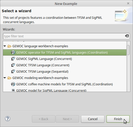
The GEMOC studio contains several examples than can be automatically deployed by using the wizard. The deployment of a BCOoL specification should be done in the language workbench. To do so, it is necessary to go to New > Example > GEMOC language workbench examples as is shown in the Figure 2.
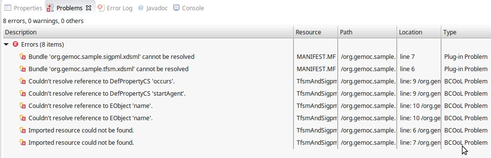
The language workbench must also contain the languages that are used by the BCOoL project. For instance, for the operator between the SigPML and TFSM languages, the SigPML and TFSM projects must be deployed in the language workbench. If the corresponding languages are not deployed, we get no resolved problems (see Figure 3). These languages can be deployed by doing New > Example > GEMOC language workbench examples.
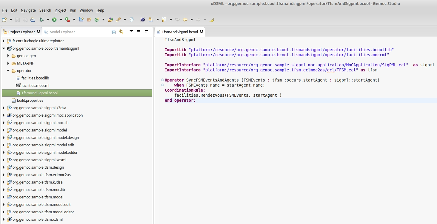
Once deployed, it is necessary to do Project > Clean in order to make the studio to find all the dependencies. The resulting language workbench should look as in the Figure 4. In this example, the directory operator contains the BCOoL specification. The project has already the BCOoL Nature, which makes compile automatically the BCOoL specification into a QVTo transformation and stores it in the /gemoc-gen directory.
Once a BCOoL specification is deployed in the language workbench, it can be used in the modeling workbench to automate the coordination of models. We show this in the section Coordinating Model Execution.
Here we explain how to create a BCOoL project from scratch in the language workbench. To do so, it is necessary to first create an empty project by doing File > New > Other > General Project. Then, it is necessary to convert the project to a plugin by doing New > Configure > Convert to plugin. Finally, it is necessary to add the XText and BCOoL Nature. By doing so, we ensure the correct behavior of the XText mechanisms of scoping and the automatically compilation of the BCOoL specification.
Eclipse propose several way to deploy and distribute the language created using the GEMOc approach. The most appropriate method will depent on the main usage.
Basicaly it consist in launching the plugins of the language using PDE (Plugin Development Environment) offerd by Eclipse.
Some Eclipse articles describe this process:
The language designer can test the language he is designing by launching a new Eclipse runtime from his development workbench.
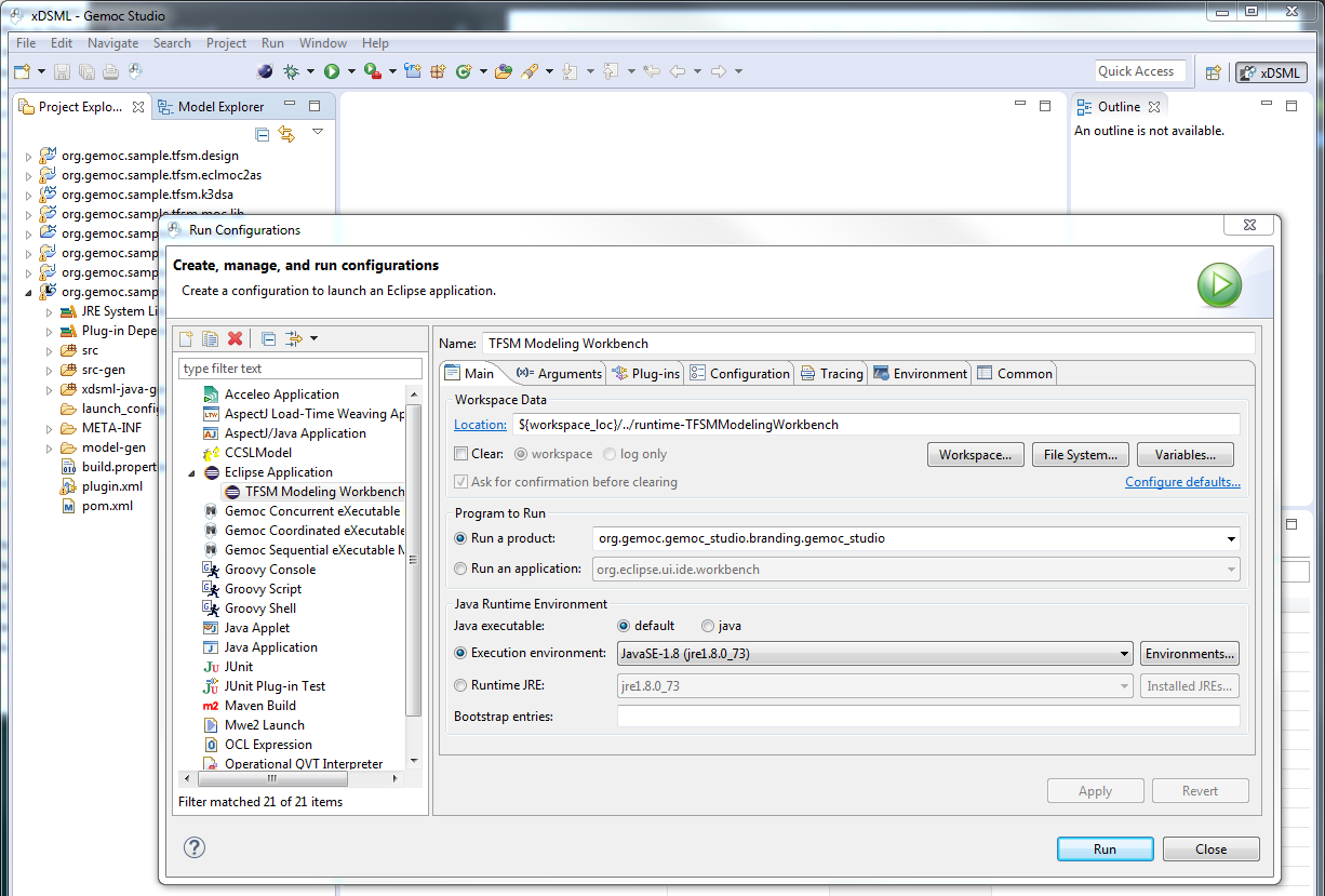
This is done by creating a run configuration. Select "run / run Configurations" Double click on "Eclipse Application" and change the name "New Configuration" into "<YourSuperLanguage> Modeling Workbench". We can now click "Run" to start the new runtime Eclipse which indeed corresponds to the Modeling Workbench for your language.
Tip
This mode offer some fine control. For example, it is possible to put breakpoint in the DSA code in order to finely develop them.
Distributing the language concist in distributing the plugins. This typically could be done via an update site or a full eclipse package (RCP application).
- The update site will allow to install the language in an existing Eclipse.
- The RCP methodoly will allow to create an application with a dedicated set of plugins including the language. This application could look like a classic eclipse IDE (including java, etc) or be completly customized for a given purpose by providing only required tools.
The GEMOC Modeling Workbench, intended to be used by domain designers: it allows creating and executing models conformant to executable DSMLs.
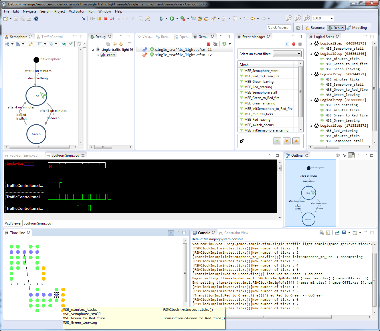
Figure 7.1. Screenshot of GEMOC Studio Modeling Workbench on the TFSM example (execution and animation).
As seen in Section Section 2.2, “Defining a Concrete Syntax”, an xDSML can provide different concrete syntaxes.
After defining your editor with Sirius (see Section 2.2.2, “Defining a Concrete Syntax with Sirius” for more details about Sirius), you can use your editor as described in the Sirius User Manual.
If you have defined a debug representation using Section 4.1, “Defining a debug representation”. You can use the following actions to start a debug session and toggle breakpoints.
As the GEMOC Studio offer different engines that requires specific configurations, it currently offers one launch configuration per engine. The views offered when running or debugging a model will also vary depending on the execution mode and the engine kind.
The GEMOC Studio currently embed 2 engines: - a sequential engine with its launch configuration - a concurrent engine with its launch configuration
Both launch configurations offer a Run and a Debug mode.
Run and debug are configured using the launch configuration. An example of configuration:
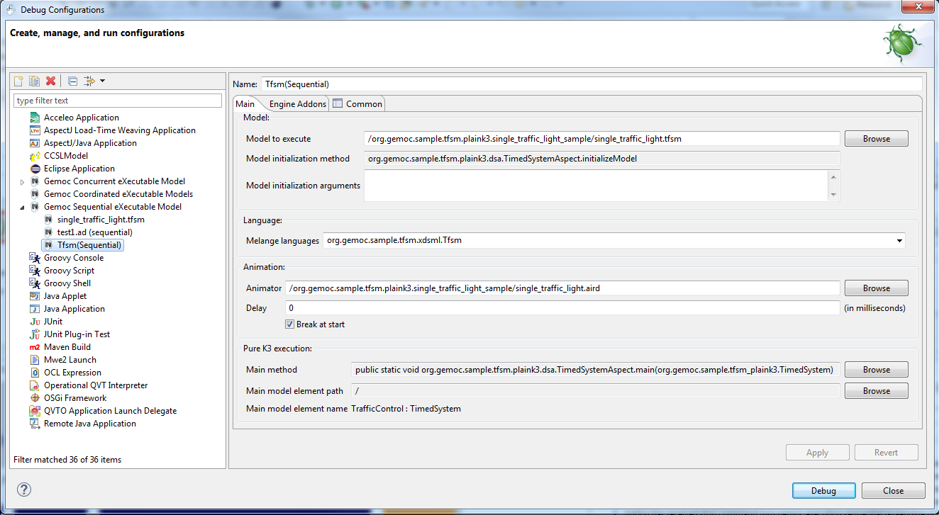
- Model to execute : this is the model that will be executed
- Model initialization method and argument : if the choosen language has a valid method with the
@InitializeModelannotation in its DSA, the field Model initialization method will be set and this method will be called before launching the animation. - Model initialization arguments : optional string arguments that can be passed to the initialization method. (one string per line)
- Melange languages : this field allows to select among the languages defined in Melange.
- Main method : the name of the method that can be used to start the engine. The possible value are specified by the language designer in the language definition by adding an
@Mainannotation on methods in the DSA. - Main model element path : after having selected a main method, use the browse button to select a model element on wich this method will be called. This field presents its path in the model, the following field Main model element name displays a human readable name for this element.
The break at start tells to the debugger to add a virtual breakpoint on the first instruction that will run.
Note
@Main and @InitializeModel annotations used to declare possible methods used in this launcher are detailed in Section 3.1.1, “Defining the Domain-Specific Actions (DSA) Project for Sequential language”.
The run mode is the fastest way to execute a model. The execution cannot be paused. It can however be stopped. It offers a limited set of views :
- the Engine View allows to stop a running model.
- the MultiBranch Timeline View is displayed at the end of the execution in order to check the resulting execution trace.
If more feedback is required, please use one of the frontend or backend available for the xDSML, see Backends and frontends.
In debug mode, the engine offers more control over the execution. It allows to pause, add breakpoints, and execute the model in a step by step mode.
It reuses the Eclipse Debug perspective and some of its views and adds some Gemoc specific views.
- the Engine View allows to stop a running model.
- the Animation Manager View is displayed and updated in real-time during the simulation. It can display both an animation layer and a debug layer.
- the Debug View. This view presents an interface for Step by Step execution of the model.
- the Variable View. This view presents the Runtime Data as a (EMF based) tree.
When running a simulation in Debug mode, it is configured to activate automatically the Debug layer and the Animation layer in the Animation view.
On the engine addon tab, one can activate several optional addons.
- the MultiBranch Timeline View can be displayed during all the simulation.
- the MultiDimensional Timeline View can be displayed during all the simulation.
The engine view displays a list of execution engines and their status:
- number of execution steps,
- current running status.
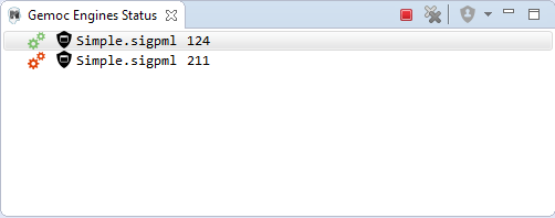
The buttons available on the top right of this view respectively allow to:
- Stop the selected engine (red square button)
- Remove previously stopped engines from the view (crosses button)
The Multidimensional Timeline view provides an interactive representation of the execution trace being captured. When double-clicking on a previous state represented in the timeline, the model is brought back into this state. Moreover, the timeline represents all the different dimensions captured in a trace, each being the sequence of values taken by one specific element of the model. When double-clicking on a value that was reached by an element, the complete model is brought back in the state corresponding to this value.
In this mode, the Debug interface is extended with backward actions that behave similarly to their forward counterparts, but follow execution steps in the opposite direction:
 StepBack Into
 StepBack Out
 StepBack Over
Warning
When going backward then forward again, the execution is a kind of replay where only the model is updated. The DSA operations are not run. The DSA will run again normally when the engine will try to run the last Step in the timeline.
Note
This view currently works only with the Sequential engine. We’re working on extending its use to concurrent model execution too.
MutiDimensional Timeline. 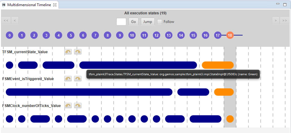
Warning
Formerly known as Event Scheduling Timeline view, this view is limited when run in Sequential. Since there is no choice of Logical Step like with the concurrent engine, the branch mechanism is disabled and this view presents only a single line.
However, despite the Multidimensional trace, this view does not require to generate a specific trace addon for the language.
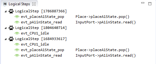
This view represents the line of the model’s execution. It displays:
- the different steps executed by the engine. Steps that have completely finished (ie. operation has returned) are shown in blue. Unfinished Steps are shown in yellow.
- the model specific events for each step.
Note
This view is enabled/disable in the launch configuration by checking "Event Scheduling Execution tracing" in the Engine Addons tab.
Sequential Execution MultiBranch Timeline. 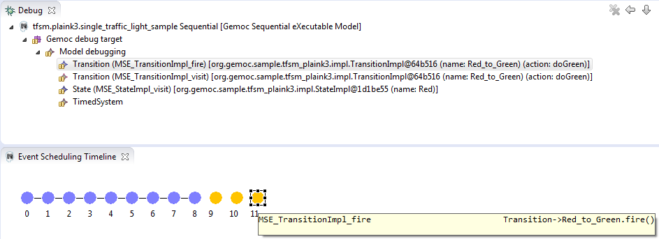
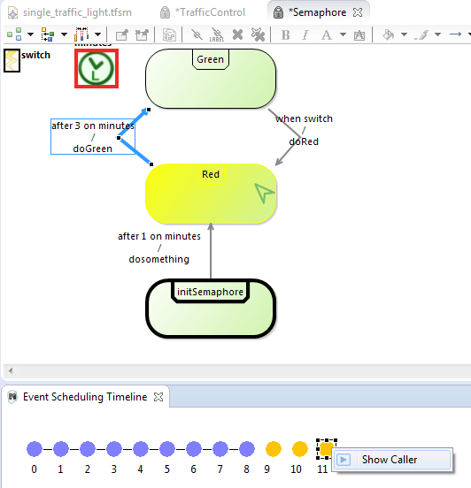
It is possible to select a logical step and use the contextual menu to show its caller by selecting the corresponding model element in the Sirius editor:
If you have defined a debug representation using Section 4.1, “Defining a debug representation”. You can use the following actions to start a debug session and toggle breakpoints.
A decorator is shown on all element holding a breakpoint. The decorator also reflects the state of the breakpoint:
- enabled
- disabled
When you hit a breakpoint on an element and are debugging with the decider "Step by step user decider", in order to restart the execution you must clic the resume button from the debug perspective. Then don’t forget to select the next logical step to execute. Do the same when debugging in step by step with the decider "Step by step user decider".
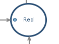
While executing you can visualize execution data. This setting must be defined by hand since the data are language dependent (see Section 4.1, “Defining a debug representation” for more details). Here the current state is decorated with a green arrow.
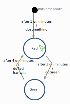
The default definition highlights the current instruction in yellow.
This view is part of the Debug perspective. It presents an interface for Step by Step execution of the model.
When an execution is paused, this view presents a stack containing all ongoing steps, with the last started step at the top of the stack.
At the bottom of the stack is a particular stackframe named Global context.
When selected, this stackframe displays the runtime data in the Variable View.
When paused, the usual debugging tools (step into, step over and step return) can be used to control the execution step by step. With the multidimentional trace enabled, the execution can be controlled backward using the ![]() StepBack Into,
StepBack Into,
![]() StepBack Out and
StepBack Out and
![]() StepBack Over commands.
StepBack Over commands.
Debug and Variable views with the sequential engine. 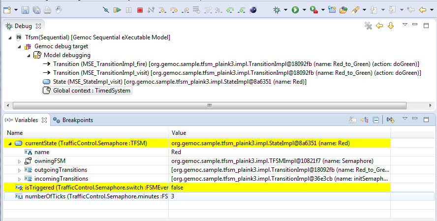
Note
In order to improve the look and feel in Debug and Variable views with the sequential engine, the icons have been customized using the technique described in Section 2.2.3, “Defining a Concrete Syntax with EMF”
This view is available on the Debug perspective. When an execution is paused, this view presents the current Runtime Data of the model.
Note
To control which Runtime Data should be presented in the Variable view, you need to set an EAnnotation with nsURI set to aspect on the corresponding EAttributes, EReferences or EClass in the ecore metamodel.
Tip
When the execution is paused, it is possible to edit the values in this view and then manually change the Runtime Data of the model.
If the Multidimenstional trace is activated, this tip works only if the execution is paused on the last instraction of the trace.
Run and debug are configured using the launch configuration. An example of configuration:
- Model to execute : this is the model that will be run
- Melange languages : this field allows to select among the languages defined in Melange.
Decider : this field allows to select the solver strategy used by the engine when several Logical Steps can be triggered. Possible choices are :
- Solver proposition : the solver internal strategy will be used to select a Logical Step
- Random : will randomly select one of the available Logical Step (warning: execution cannot be reproduced when using this Decider)
- Ask user : (available only in Debug mode), this option will use the Logical Step View or the MultiBranch Timeline View to present the available Logical Steps and pause if there are more than one Logical Step. The user will then need to click on one of the Logical Step to continue.
- Ask user (Step by step) : (available only in Debug mode), this option is similar to the previous one. However, it will pause on every Logical Step, even if there is only one Logical Step that can be triggered. This is more or less equivalent as putting a breakpoint on every MSE of the language.
More Deciders will be developed (for example for playing predefined scenario).
In run mode, it offers the faster way to run the model. It cannot be paused. However, you can stop it. It offers a limited set of views :
- the Engine View allows to stop a running model.
- the MultiBranch Timeline View is displayed at the end of the execution in order to control the resulting execution trace.
If more feedback are required, please use one of the frontend or backend available for the xDSML, see Backends and frontends.
In debug mode, the engine offers more control on the execution. It allows to pause, add breakpoint, and run in a step by step mode.
It reuses the Eclipse Debug perspective and some of its views and add some GEMOC specific views.
- the Engine View allows to stop a running model.
- the MultiBranch Timeline View can be displayed during all the simulation.
- the Logical Steps View is available for concurrent execution.
- the Stimuli Manager View is displayed during all the simulation.
- the Animation Manager View is displayed during all the simulation. It can display both an animation layer and a debug layer.
- the Debug View. This view presents an interface for Step by Step execution at the Logical Step level or even at the DSA level.
- the Variable View. This view presents the Runtime Data as a (EMF based) tree.
When running a simulation in Debug mode, it is configured to activate automatically the Debug layer and the Animation layer in the Animation view.
The break at start tells to the debugger to add a virtual breakpoint on the first instruction that will run.
Backends and frontends offer additionnal view that can respectively display informations from the running model or provide event input to the running model.
These backends and front ends usually open dedicated views. These views are always opened in all modes (Run or Debug).
The engine view displays a list of execution engine and their statuses:
- its number of execution steps,
- its current running status,
- and its logical steps deciding strategy.
The buttons available on top right of this views respectivley allows to:
- Stop the selected Engine (red square button)
- Remove previously stopped engines from the view (crosses button)
- Change the current logical step decider (shield button).
Tip
When running in debug mode, You can easily "pause" an engine running with a solver or random decider by clicking on the change logical step decider (the shield button will be green when run in debub mode) this will automatically switch to the "Step by step decider". To restart, simply select back an automatic decider (solver or random) and select the next step in the LogicalStep view.
The logical steps view displays the list of possible future executions. This list is provided by the solver. This view is organized around a tree. For each logical step, its underlying events can be seen and possibly for each event the associated operation is visible.
Note
This view displays nothing when execution runs in "run mode", per say this view is only of use when running in "debug mode".
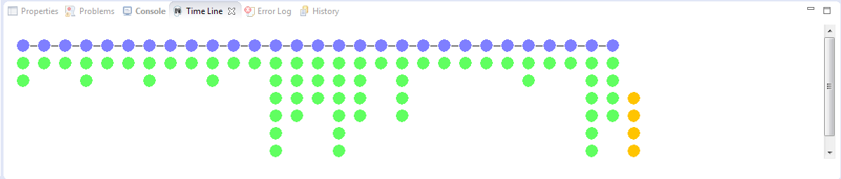
Formely known as Event Scheduling Timeline view, this view represents the line of the model’s execution. It displays:
- the different logical steps proposed by the solver in the past in blue color,
- the selected logical steps at each execution step in green color,
- and the possible future logical steps in yellow color,
- the model specific events for each logical step.
Note
This view can be enabled/disable in the launch configuration by checking "Execution tracing" in the Engine Addons tab.
Note
The possible future logical steps are shown under the condition that the model is executing.
In addition to displaying information, it also provides interaction with the user. During execution, it is possible to come back into the past by double-clicking on any of the blue logical steps. It does three things:
- it resets the solver’s state to the selected execution step,
- and it resets the model’s state to the selected execution step,
- it also forks the current timeline and create a new branch of execution.
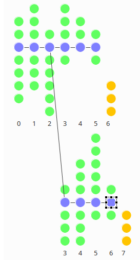
It is also possible to select a logical step and use the contextual menu to show its caller in the Sirius editor:
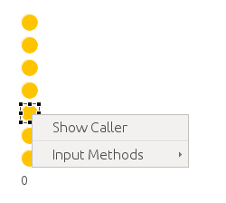
The Stimuli Manager view display the list of MSE and has interactions with the Logical Steps view.
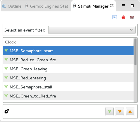
When selecting an MSE you can constrain it by clicking on :
- Green down arrow : no user constraint for this MSE in the next LogicalStep
- Orange down arrow : forbid tick of this MSE in the next LogicalStep. The solver will propose only solutions where this MSE doesn’t tick.
- Orange up : force tick of this MSE in the next LogicalSteps. The solver will propose only solutions where this MSE ticks.
Depending of your choice, the list of proposals will be changed in the Logical Steps view.
Moreover selecting an element in the Logical Steps view will highlight the MSE involved in the Stimuli Manager view.
Tip
This Stimuli Manager view can be used to manually simulate external events.
If you have defined a debug representation using Section 4.1, “Defining a debug representation”. You can use the following actions to start a debug session and toggle breakpoints.
A decorator is shown on all element holding a breakpoint. The decorator also reflects the state of the breakpoint:
- enabled
- disabled
When you hit a breakpoint on an element and are debugging with the decider "Step by step user decider", in order to restart the execution you must click the resume button from the debug perspective. Then don’t forget to select the next logical step to execute. Do the same when debugging in step by step with the decider "Step by step user decider".
While executing you can visualize execution data. This setting must be defined by hand since the data are language dependent (see Section 4.1, “Defining a debug representation” for more details). Here the current state is decorated with a green arrow.
The default definition highlights the current instruction in yellow.
This view is part of the Debug perspective. It presents an interface for Step by Step execution at the Logical Step level or even at the DSA level. When an execution is paused, this view presents the current Logical Step.
When paused on a Logical Step, the Step over command allows to go to the next Logical Step. The Step Into command allows to run separately each of the internal DSA calls associated to the Logical Step.
One benefit of assigning an execution semantics onto a DSL is to pave the way for exhaustive exploration. Exhaustive exploration is a technique used in complex and safety system design to ensure the correct adequacy between the system requirements and the real behavior of the system. This is made possible by exploring and verifying properties on an exhaustive finite state space of the system representing the whole set of relevant configurations your system may reach.
Gemoc provides the first step towards exploration and verification by building the graph of all the possible schedules of a system model constrained with MoCCML. It can then be used in a model-checking tool to verify behavioral properties of the MoCCML models. Thanks to Gemoc approach the execution model is explicited and can be manipulated to for instance:
- Verify temporal logic properties (safety and liveness) on the state space graph structure;
- Extract a schedule that optimizes specific objectives;
- Extract system properties by static analysis of an event-graph representation of the execution model.
In the Gemoc approach the steps toward exploration and verification during language design are described in Section 3.2.3, “Exhaustive Exploration and Verification at Language Design Time”.
Besides the steps toward exploration and verification during modeling design are:
- Generate a model for an exhaustive exploration tool using the configuration file;
- Invoke ClockSystem's services to generate a finite state space of the system;
- Formalize a set of properties to verify(in CDL language for instance);
- Use a model checking infrastructure to perform the verification of properties on the finite state space(like OBP).
The flow toward exhaustive exploration and verification in Gemoc is presented in figure Figure 3.3, “The exploration and verification flow in Gemoc” and described in the following sections.
ECL specification is the starting point toward exploration. In this specification we define events associated with the actions of the DSA and also events associated with the DSE events. On these event bindings we apply the MoccML relations of the MoC Library to schedule the events. A finite state space of a system uses such scheduling constraints and therefore is generated from using a transformation:
In the Modeling workbench where the DSL instance model is realized, the transformation T2 takes as input the instance system model to generate a MOCC instance model described in ClockSystem specification format.
Th call the transformation right-click on your model → ![]() Exhaustive Exploration →
Exhaustive Exploration → ![]() Generate ClockSystem file from DSL model.
Generate ClockSystem file from DSL model.
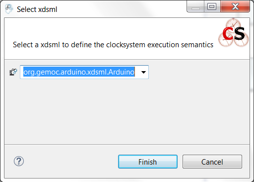
A wizard allows you to select one xdsml project referencing a concurrent model, click on finish to execute the transformation. T2 generates the .clocksystem file corresponding to the Mocc-based specification model to take as input in ClockSystem.
ClockSystem is a meta-described clock-constraint engine developped during Gemoc which embeds a formal model of logical time. It relies on the primitives provided by Clock Constraint Specification Language (CCSL) defining a simple yet powerful toolkit for logical time specifications. It also extends the CCSL language, through an automata-based approach, with domain-specific user-defined operators and provides an embedded DSL for writing executable specification in a language close to the abstract CCSL notation.
ClockSystem toolkit provides the possibility to perform exhaustive reachability analysis of relation specifications (e.g. MoCCML or CCSL specifications). The possibility to exhaustively explore the state-space of a given specification paves the way to verification of properties by model-checking as such an interface with the OBP model-checking toolkit was developed.
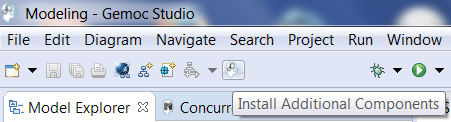
ClockSystem consists of an image and a Pharo VM which depends on the operating system. Their integration in Gemoc studio can be realized through the discovery mecanism. To activate discovery mecanism click on the Gemoc icon in toolbar as illustrated Figure 9.2, “Discovery”.
Select ClockSystem add on Figure 9.3, “Discovery Components” and click on Finish.
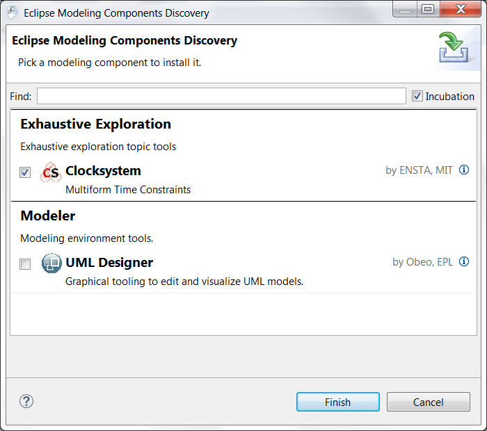
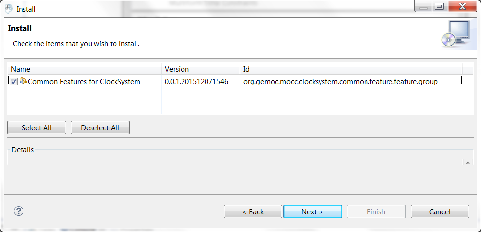
Select the unique feature and Next as illustrated in Figure 9.4, “Discovery Clocksystem”. Then again select Next.
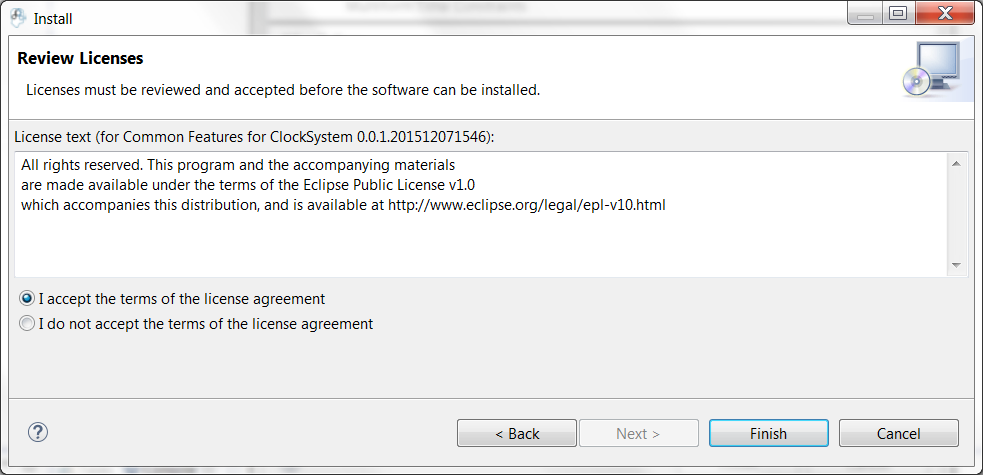
Approve the licence and click Finish. Gemoc must be restarted(this should be automatically prompted to the user).
Note
ClockSystem VM and Image will be extracted in your default temporary folder at the first call of Clocksystem services. Although Gemoc provides an action to invoke ClockSystem, it can be also used as a standalone application outside of Gemoc studio.
Calling ClockSystem from Gemoc studio on the file generated by T2(.clocksystem) generates exploration results including a LTS.
To invoke ClockSystem right-click on the ClockSystem file .clocksystem→![]() ClockSystem →
ClockSystem →![]() Execute ClockSystem .
Execute ClockSystem .
Generated files are:
- .lts file stores labeled transition system (LTS) which represents all the possible configurations the system can reach.
- obp.lts file stores labeled transition system (LTS) in a format understandable by OBP.
- .results extract global information about the size of the explored graph(number of states, transitions and time of exploration).
- full.gml is the representation of the LTS graph stored in a Graph Modelling Language (GML) format providing a simple syntax to represent graph.
- fcr.gml is the representation of the LTS graph with the coincidences flatten for Fiacre stored in GML.
- .mtx stores the representation of the LTS graph as a Matrix Market providing a simple and standardised way to exchange matrix data.
The picture below illustrates an instance and its corresponding exploration graph Figure 9.6, “Exploration Graph for an Instance”.
The properties are expressed using assertions or/and observer automata with appropriate variables and clocks of the model instance. Several groups of properties are interesting to verify at different level in the Gemoc process. Properties can be expressed on the model instance based on variables and clocks of one (or several) model element(s) and allows to check deadlocks, precedency between events, reachability etc… The expression of the properties are model dependent so on each instance you must rewrite the properties. However properties can also be related to representative instances which are based on a mapping between a generic abstract syntax, or a metamodel pattern and a mapped Mocc on this abstract syntax. In this approach we are looking for a reducing number of instance to verify and increase the generality of the verification approach. A representative instance is a model that spreads a configuration that is structuraly relevant regarding the metamodel pattern. On this representative model, we can verify properties tightly linked with the MoCCML semantics.
For instance the model Figure 9.6, “Exploration Graph for an Instance” can be considered as a representative instance of a Classifier-Relationship metamodel pattern. On it wish to apply a Mocc SDF semantics and therefore generic properties can be expressed as: - If all the input ports of a Block haven’t enought data to consume then the Block canno’t execute. - If the number of data of an output port is less than the Connector capacity minus the current size of the Connector then the Block can execute. - In any case, the current size of a Connector canno’t exceed its capacity.
These properties are representatives of the Mocc and could be verified for every model. So we verify these properties on the representative model instance, to improve the trust on our pattern.
Properties have to be formalized for a checking tool. As ClockSystem provides a connector to OBP model-checking infrastructure we present a CDL formalization of the properties, which is also an OBP compatible format. The CDL formalism provides 3 distincts constructs for expressing safety and bounded-liveness properties predicates to express invariants over states, observers to express invariants over execution traces and property patterns, for simplifying the expression of complex properties.
Properties are described using CDL syntax and must be specified at instance level therefore the name of the processes or variable used in properties reflects the names and variables of instances within the verified model. CDL properties can be written in a simple text file with the extension .cdl.
For instance we impose our model to respect a SDF-like semantics and therefore we are interested in verifying properties that defines SDF: - If all the input ports of a Block haven’t enought data to consume then the Block canno’t be executed. - The current size of a Connector canno’t exceed its capacity. An internal moc variable called current_size increments or decrements respectively if a data is push or pop within the Connector, and this variable must be always lower than the maximal capacity of the Connector.
In the listing below three properties are encoded in CDL.
// Size of connector A to B never exceeds its capacity
predicate p2 is { {connectorAB}1 : currentsize <= 4 }

// If Output channel is full the Block does not execute
predicate p3 is { {connectorBA}1 : currentsize + {outport1}1 : rate <= {connectorBA}1 : capacity }
property o1 is {
	start -- / p3 // -> s1
	; s1 -- / / eB / -> reject
	; s1 -- / not p3 / / -> start
}

// Select the properties to be checked
cdl representativeInstance is {
	properties
	, o1
	assert p1
	; assert p2
	main is {skip}
}- The size of channels between A and B canno’t exceed the capacity of the connector. This is described with predicates p1 and p2 that check if the fifo size limit is reached.
- It is not possible to write in a Connector if it is full. This is checked via the observer automata o1 for one Connector. If the size of the Connector plus the output rate exceed the size limit and if then Block execute(eB) the observer o1 goes to reject state.
The OBP Observation Engine checks a set of CDL properties using reachability strategy (breath-first-search algorithm) on the graph induced by the parallel composition of the system, with its contexts.
In the context of Gemoc OBP OBP requires two input files i.e the LTS generated from ClockSystem and the CDL properties. This operation has to be done manually and is not part of the Gemoc studio tooling since OBP is not integrated to the studio.
In the modeling workbench, a system designer can use the BCOoL operators previously defined in the Language Workbench to automate the coordination of models. To do so, the modeling workbench includes BFLoW, a simple language to specify how BCOoL operators are applied between models. Conjointly with the GEMOC Coordinated Execution Engine, the BFLoW specification can be used to coordinate, and then, execute models.
The GEMOC studio includes examples that can be automatically deployed into the modeling workbench by using the wizard. We recommend to start with such examples.
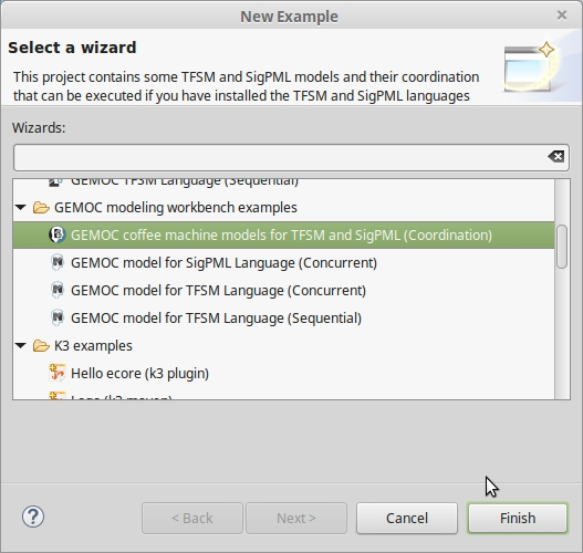
The GEMOC studio contains several examples than can be automatically deployed by using the wizard. The deployment of an example should be done in the modeling workbench. To do so, it is necessary to go to New > Example > GEMOC modeling workbench examples as is shown in the Figure 1.
The example contains the models together with a BFLoW specification that can be used to coordinate them. Note that the language workbench has to contain the languages and the BCOoL project used by the example. For instance, in the case of the example of the Coffee Machine by using the TFSM and SigPML languages, the language workbench has to contain the languages TFSM and SigPML and the BCOoL operator defined between these languages.
BFLoW is simple language that allows to specify how a particular system must be coordinated. To do so, BFLoW enables a system designer to specify how a set of BCOoL operators are applied between a set of models. While in the language workbench BCOoL is used to specify operators between languages, in the modeling workbench BFLoW is used to specify how these operators are applied to coordinate a particular system.
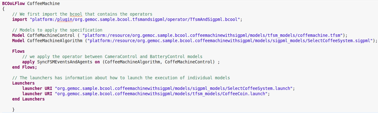
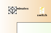
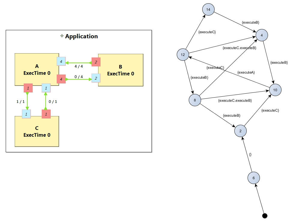
Figure 2 shows the BFLoW specification for the coffee machine example. A BFLoW specification contains information about the BCOoL used and the models to be coordinated. Then, each flow defines what operator is applied and between which models. Note that the order of the models passed as parameters matters. The order must correspond with the operator definition. In addition, the BFLoW may contain information about the launchers used to launch the execution. When launchers are not defined in the BFLoW, it is necessary to define an output model in the beginning of the BFLoW specification (see CoffeeMachinewithoutLaunchers.bflow in the example project org.gemoc.sample.bcool.coffeemachinewithsigpml).
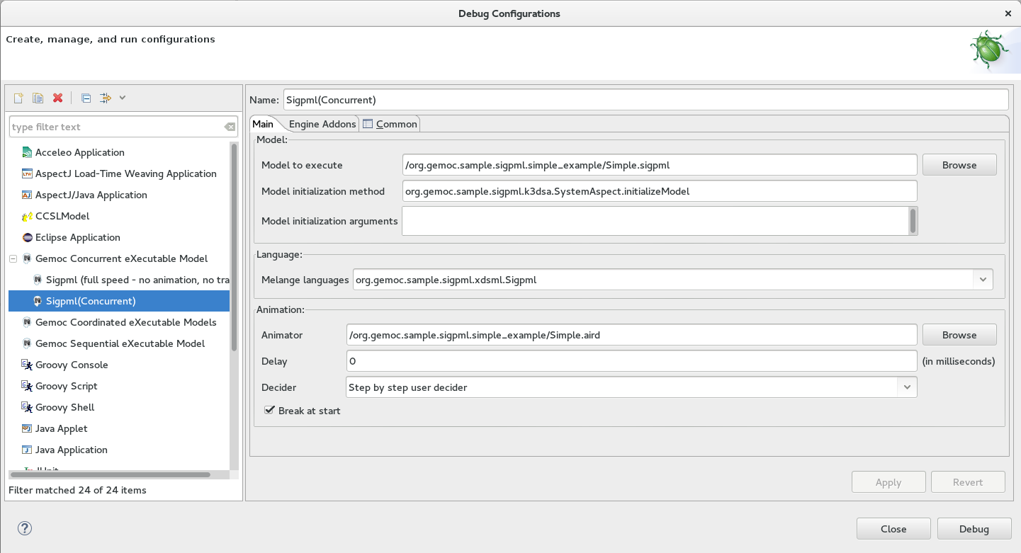
To execute the coordinated system, we first need to go to Debug Configuration and configure the Gemoc Coordinated eXecutable Models as shown in the picture.
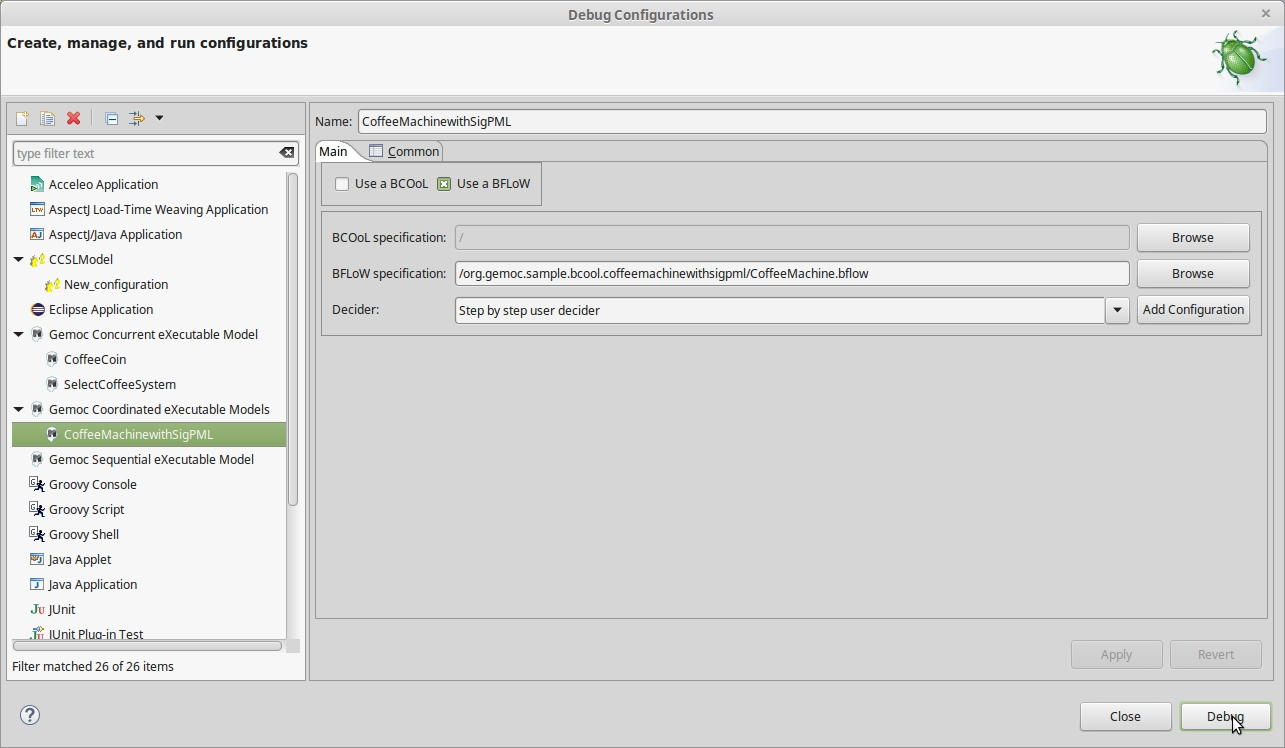
The execution can be launched by using either a BCOoL or a BFLoW specification. In the first case, the BCOoL specification is in the modeling workbench and the model of coordination is built by applying the BCOoL specification between all the models. In such a case, it is mandatory to specify the launchers of the individual models before to launch the execution.
In the case that a BFLoW specification is used (as shown in Figure 3), the model of coordination is built by using the BFLoW specification. If the BFLoW specification does not define the launchers, they must be manually defined by clicking on "Add Configuration" (see Figure 4).

Once launched, the engine provides several options to drive the execution of the models. For instance, it enables a system designer to select the next valid execution step (see Figure 5). Also, the workbench provides the animation of models.
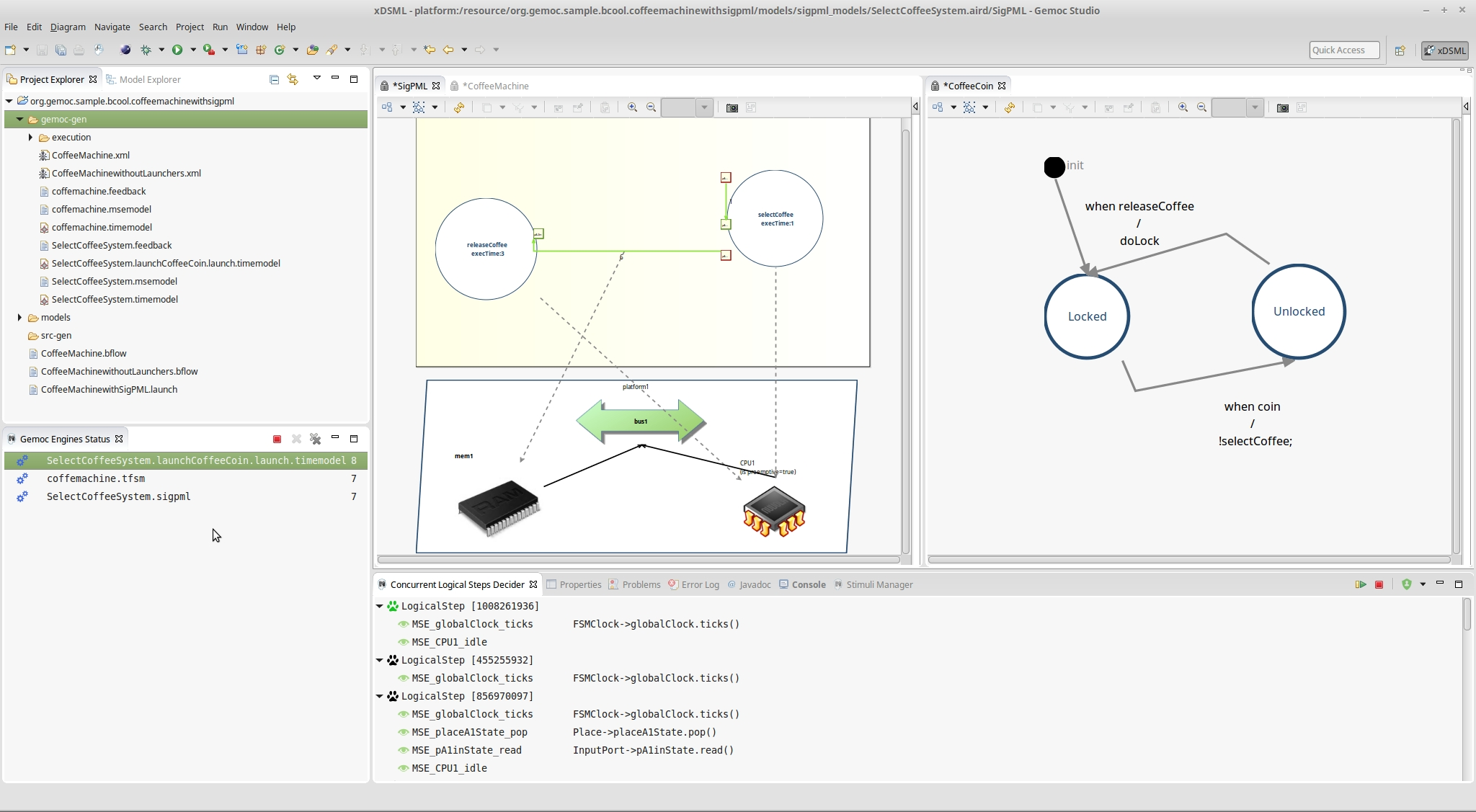
For further information about BCOoL please visit BCOoL site. If you are experimenting problems during the compilation of the example, please email to me.
The bibliography lists some useful external documents. For a more complete list, please refer to the publications section on http://gemoc.org site.
Articles
[globalizing-modeling-languages] Globalizing Modeling Languages (Benoit Combemale, Julien Deantoni, Benoit Baudry, Robert France, Jean-Marc Jezequel, Jeff Gray), In Computer, IEEE, 2014.
- AS
- Abstract Syntax.
- API
- Application Programming Interface.
- Behavioral Semantics
- see Execution semantics.
- CCSL
- Clock-Constraint Specification Language.
- Domain Engineer
- user of the Modeling Workbench.
- DSA
- Domain-Specific Action.
- DSE
- Domain-Specific Event.
- DSML
- Domain-Specific (Modeling) Language.
- Dynamic Semantics
- see Execution semantics.
- Eclipse Plugin
- an Eclipse plugin is a Java project with associated metadata that can be bundled and deployed as a contribution to an Eclipse-based IDE.
- ED
- Execution Data.
- Execution Semantics
- Defines when and how elements of a language will produce a model behavior.
- GEMOC Studio
- Eclipse-based studio integrating both a language workbench and the corresponding modeling workbenches
- Language Workbench
- a language workbench offers the facilities for designing and implementing modeling languages.
- Language Designer
- a language designer is the user of the language workbench.
- MoCC
- Model of Concurrency and Communication
- Model
- model which contributes to the convent of a View
- Modeling Workbench
- a modeling workbench offers all the required facilities for editing and animating domain specific models according to a given modeling language.
- MSA
- Model-Specific Action.
- MSE
- Model-Specific Event.
- RTD
- RunTime Data.
- Static semantics
- Constraints on a model that cannot be expressed in the metamodel. For example, static semantics can be expressed as OCL invariants.
- xDSML
- Executable Domain-Specific Modeling Language.
A
- Animation Manager, Sequential Debug mode, Concurrent Debug mode
B
- BCOoL, What is BCOoL?
- Both representations (graphical or textual) can be used for edition of models, Presentation of the MoCCML Editor
C
- CDL, Exhaustive Exploration and Verification at Model Design Time
- ClockSystem, Exhaustive Exploration and Verification at Model Design Time, Generating inputs for Exhaustive Exploration tools : T2 at Modeling Level, ClockSystem, Description, Using ClockSystem, Expressing Properties (CDL Formalization)
- Concurrent Engine, Executing model with the Concurrent Engine
D
- Decider, Concurrent General options
- DSA, Generating inputs for Exhaustive Exploration tools : T1 at Language Level, Generating inputs for Exhaustive Exploration tools : T2 at Modeling Level
- DSE, Generating inputs for Exhaustive Exploration tools : T1 at Language Level, Generating inputs for Exhaustive Exploration tools : T2 at Modeling Level
E
- ECL, Introduction, Exhaustive Exploration and Verification at Language Design Time, Generating inputs for Exhaustive Exploration tools : T1 at Language Level
- EMF, Defining a Concrete Syntax with EMF
- EMF Tree Editor, Editing model with EMF Tree Editor
- Engine, Sequential Run mode, Sequential Debug mode, Concurrent Run mode, Concurrent Debug mode
G
- GEMOC Language Workbench, Overview
I
- import, Import Language
L
- Language Designer, Overview
- Language Integrator, Overview
- Language Workbench, Overview
- Logical Step, Concurrent General options, Debug View
M
- MoCCML, Introduction, Exhaustive Exploration and Verification at Language Design Time, Generating inputs for Exhaustive Exploration tools : T1 at Language Level, Exhaustive Exploration and Verification at Model Design Time, Description, Defining Properties
- MoccML, Generating inputs for Exhaustive Exploration tools : T1 at Language Level, Generating inputs for Exhaustive Exploration tools : T2 at Modeling Level
- Modeling workbench, Modeling workbench overview
- mtl-gen, Generating inputs for Exhaustive Exploration tools : T1 at Language Level
- MultiBranch Timeline, Sequential Run mode, Sequential Debug mode, Concurrent Run mode, Concurrent Debug mode
- MultiDimensional Timeline, Sequential Debug mode
R
- Runtime Data, Sequential Debug mode, Variable View, Concurrent Debug mode, Variable View
S
- Sequential Engine, Executing model with the Sequential Engine
- Sirius, Defining a Concrete Syntax with Sirius, Defining a debug representation, The debug representation wizard, Debug layer, Editing model with Sirius
- Sirius), Editing model with Sirius
- Stimuli Manager, Concurrent Debug mode
T
- TFSM, Modeling workbench overview
- Language Workbench, Overview
- Modeling workbench, Modeling workbench overview